DC, doesn't matter. Right hand rule...
Other to ground or negative.
Must be rated at supply volts and DC of course.
Other to ground or negative.
Must be rated at supply volts and DC of course.
What size wire should I run from the alternator to the solenoid and from solenoid to external regulator? I heard if using to small of wire I could get voltage spikes not sure if that’s true or not
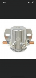
I was told by the manufacturer of the alternators I have to use this solenoid. 1 wire comes from the charging post to the solenoid the other side of the solenoid connects to the switches power terminal of the regulator . Then I have a ground wire and a switched ign wire to turn the solenoid on and off .
He told me to use this in order to isolate the 16 volt system from the factory charging system
He told me to use this in order to isolate the 16 volt system from the factory charging system
Maybe someone else can answer this. I don't understand why you'd ever disconnect the alternator from the regulator.
Not disconnecting anything . Im using the solenoid for switched power for the external regulator I need the switched wire at 16 volts not 12
Are you simply asking about the 2 small terminals?
Those are for 12v. They can be switched with the ignition on/off.
Those are for 12v. They can be switched with the ignition on/off.
Why do you need a solenoid?
Methane / propane gas, air, refrigeration?
And please do not play with wires inside the alternator, the results are not reliable.
More clearly, you want to switch a 16V line using a 12V solenoid?
Go ahead, see the ratings are adequate for the load you want switched by the solenoid.
Methane / propane gas, air, refrigeration?
And please do not play with wires inside the alternator, the results are not reliable.
More clearly, you want to switch a 16V line using a 12V solenoid?
Go ahead, see the ratings are adequate for the load you want switched by the solenoid.
Last edited:
This post went crazy ! I’m not playing with any wire inside the alternator Im not disconnecting anything !
I have 2 aftermarket alternators with external regulators all I asked is what size wire I would use to wire up the external regulator and solenoid.
Yes I need the solenoid to make a switched power circuit since the 16 volt charging system is completely isolated from the 12 volt system .
The Alternators regulators and solenoid are what I bought from the manufacturer. This is what I was told I needed . He’s been in business a long time don’t think he would last long in the business if he was just doing guess work and selling stuff that didn’t work together
If you're not disconnecting anything, why are you using a solenoid?
Why can't you use a 12v switched source that's controlled by the ignition to control the solenoid?
The control terminals of the relay could be powered by a 16g wire.
The page I linked to shows using a diode on the coil. These solenoids can produce a high-voltage spike when the 12v control power is cut. The spike can cause damage to switches and sometimes to electronics without the diode.
I guess I didn’t explain what the solenoid is for properly .
I haven’t hooked the alternators regulators or solenoid up yet . I will be using the switched ign wire (12volts) to turn the solenoid on and off with the key .
The purpose of the solenoid is that the external regulator needs to see a switched ign wire the voltage on that wire needs to be 16 volts not 12 .
This can be done with a solenoid or a relay .
The solenoid will be wired like this . On 1 post of the solenoid I will be connecting it to the charging post of the alt on the other post I will will be wiring it to the switched ign wire on the regulator (16 volts) the turn on post of the solenoid will be wired to the switched ign wire
(12 volts) and the last post will go to ground .
He is thinking of using the solenoid as a single pole heavy duty relay, the control signal is 12 V, the load is at 16 V, that is a completely different isolated circuit.
The switch for control is a key switch.
A diode would be useful to protect the 12 V side from back emf when cutting power.
Please correct any mistakes I made.
The switch for control is a key switch.
A diode would be useful to protect the 12 V side from back emf when cutting power.
Please correct any mistakes I made.
OK, That means that the high-current terminals of the solenoid are being used to disconnect the control voltage from the regulator. Is that correct?
What kind of terminal is there on the regulator for this control voltage?
What kind of terminal is there on the regulator for this control voltage?
The control voltage is a key switched 12 V line which switches the solenoid coil.
The solenoid load terminals are controlling the 16 V line...I think.
The solenoid load terminals are controlling the 16 V line...I think.
What I'm questioning is why a 80 amp solenoid is being used to switch a control voltage, especially if the control voltage is passing through a low-current type of terminal.
Last edited:
No, we are talking opposite sides.
He is intending to control a 16 V line from alternator to charging post by connecting the coil of the solenoid through a 12V line with a key switch...I think.
The high current / load side will switch 16V, and the solenoid control coil will see 12V.
He is intending to control a 16 V line from alternator to charging post by connecting the coil of the solenoid through a 12V line with a key switch...I think.
The high current / load side will switch 16V, and the solenoid control coil will see 12V.
The control voltage I was referring to was the control voltage for the regulator, not for the solenoid.
In electric control panels, the PLC or whatever sends control signals for the relays and SSRs.
So the switching element, relay / solenoid coil, or opto-coupler, is controlled by the control signal, and the main current to be controlled is on the primary or load side of the unit.
So we were at cross purposes.
Wait for the OP to clarify, I think that is better.
So the switching element, relay / solenoid coil, or opto-coupler, is controlled by the control signal, and the main current to be controlled is on the primary or load side of the unit.
So we were at cross purposes.
Wait for the OP to clarify, I think that is better.
- Home
- General Interest
- Car Audio
- Continuous duty solenoid