Thanks. It's notable that not many producers of rubber post their dampening coefficient. So far I have only seen this from Pyrotek.If it is a significantly viscoelastic material rather than mainly an elastic one then the harder the material the greater the damping force. However, if it was significantly viscoelastic it would be reasonable to expect the damping coefficient (or equivalent) to be mentioned in the datasheet.
Would it be possible to extract or guess the dampening coefficient based on other properties?
Edit: To put it in a different way, is going off on other properties useless, without knowing the dampening coefficient?
Last edited:
Ringing the distributor and/or manufacturer and asking might get the information. I don't think it can be determined from the material properties in the supplied datasheet but reading about typical damping coefficients for similar materials from other suppliers might give you a ballpark figure. I wouldn't be surprised if the soft material has an OK damping coefficient and the hard materials a small damping coefficient making it tricky to know which produces the largest damping force.Would it be possible to extract or guess the dampening coefficient based on other properties?
Edit: To put it in a different way, is going off on other properties useless, without knowing the dampening coefficient?
In truth I haven't studied the available materials but intend to do so at some point in the near future. So please keep posting about what you find.
But remember that it is the filler material that results in the high damping of the end result. Hence the damping of the binder itself may be worthless. I doubt that the manufacturer will know the combined number since there are many different fillers.
I had missed that Arnandsway was wanting to do this and so if the damping is provided by a different material then clearly that material must be involved in any assessment of the damping coefficient for the combined materials.But remember that it is the filler material that results in the high damping of the end result. Hence the damping of the binder itself may be worthless. I doubt that the manufacturer will know the combined number since there are many different fillers.
Materials with high internal damping are usually relatively weak and tend to get combined with materials that are relatively strong. For example, concrete (strong low damping) and filler (weak high damping), plywood/fibreglass (strong low damping) and resin (weak high damping), etc...
I'm wondering how this might compare to Dr. Geddes' method of PU/microspheres. Could be easier to apply, 3M spray adhesive on both surfaces and the sheet in between. Would it hold two pieces of ply together? Probably not. Would it perform as good as PU/microsphere? Probably not.
Be curious to get some thoughts.
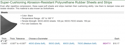
Edit: Looking at the tensile strength, it looks quite low.
Be curious to get some thoughts.
Edit: Looking at the tensile strength, it looks quite low.
Attachments
Last edited:
There are lots of options, you just have to try them. There are many different 3M sprays some very strong, others not so much. I would expect the spray route to be very expensive however as the spray is not cheap and does not go very far. I have used a lot of it in the past, but not for CLD.
Who needs evidence? Common sense and experience shows that both would happen.
I have to agree, and it's not necessarily intuitive at first glance.To perhaps take a step back from this argument, let me say that I would always assume the the enclosure is heavily damped inside, which means that pretty much only LFs below say 200 Hz are going to make it through this damping and back, but below that, of course they are felt by the cone. But the cone is not only a dead mass to a sound wave, it's well damped, but these sound waves will be felt and will modify the cones movement to the extent that they are significant.
In my case when the speaker was measured with and without its enclosure back (on axis of course.) I could not detect any differences once the box compliance (a direct result of these enclosure "reflections") and dipole effect was adjusted for. My only conclusion had to be that these internal reflections are not coming back through the cone to a significant degree.
To me, that's evidence to the contrary of your position.
Sounds waves from internal box standing waves "passing through" a speaker cone from inside the box sounds convincing but is not how it works, for that to be the case the driver would have to be porous or have gaps that air can actually pass through.
Ok, so you could perhaps make a case that a driver with a fabric surround may be slightly porous (if the fabric is not doped, which it often is) but most woofers have a non-porous rubber surround, so there is no direct air path through the woofer for the sound to "pass through" the driver.
Instead as you say any sound wave, standing wave or otherwise inside the box simply exerts a force on the inside of the cone and if that results in a change in the movement of the cone, that would affect the total sound radiated by the outside of the cone and be heard. The operative word is if.
The critical difference between a panel and woofer cone is that the cone is not a dead weight like a cabinet panel, it is electrically and mechanically damped, so will actively resist being "pushed around" by any sound waves inside the box, especially if the driver Qes is low and it has a low impedance path through the crossover back to the amplifier.
Any attempt to push the cone mechanically when the driver is connected will result in back EMF which will dissipate energy and resist movement like an electromagnetic brake. Also because the acoustic impedance match between the cone and air is quite poor the pressure wave doesn't exert much force on the cone anyway.
In the anecdotal testing I've done with cabinets that are lined but not stuffed, you can have a plain old shoebox shaped cabinet with strong acoustic standing waves in the axial dimensions of the cabinet in the 150-300Hz range that are clearly very audible (>10dB peaks) if you remove the driver and play a tone into the box, listening at the opening of the box but more or less completely inaudible when the driver is installed and is the source of the sound.
A close mic nearfield frequency response at the cone of the driver shows the tiniest little blip (fraction of a dB) at the frequency where the standing waves are forming in the box. They simply don't pass out "through" the driver in any meaningful way, and what small effect there might be could be corrected with EQ in theory if you wanted to. (But I haven't found it necessary)
Reradiation of internal standing waves "through" the cone is simply a non-issue in practice.
What is audible is secondary radiation from the panels. The panels don't have the broad band electromagnetic damping/braking of the driver cone, have large resonances of their own which can often fall near the acoustic resonances, and have many, many times larger surface area.
The audibility of internal acoustic standing waves is more about them exciting the panels with increased amplitude and those panels then reradiating the sound using their very large surface area.
If you can damp or isolate the panels from the internal acoustic standing wave it doesn't actually matter whether that internal standing wave exists in the void of the box or not...
In other words get the structure of the box right, don't worry about an acoustic standing wave forming in the void inside the box - it really doesn't matter much. (In the case of something like a bass reflex enclosure where you can't fill it with stuffing there's not much you can do about it anyway! Just isolate the panels with a layer of lining and damp the panels)
Last edited:
In other words get the structure of the box right, don't worry about an acoustic standing wave forming in the void inside the box - it really doesn't matter much.

Although in many cases this will work out fine, certain standing waves with certain driver positions might be problematic. The velocity nodes of standing waves will cause significant forces on the cone. Often the measured impedance curve is a reasonable indicator for that. Your everyday burst decay plot close range to the cone does show possible problems too. If such behavior is noticeable in normal domestic listening environments is another issue of course.In other words get the structure of the box right, don't worry about an acoustic standing wave forming in the void inside the box - it really doesn't matter much. (In the case of something like a bass reflex enclosure where you can't fill it with stuffing there's not much you can do about it anyway! Just isolate the panels with a layer of lining and damp the panels)
Although in many cases this will work out fine, certain standing waves with certain driver positions might be problematic.
Of course problems can occur if things aren't done right. I assume that the enclosure is filled with damping material, in which case what you note would not be the case.
But I do agree that blips on the impedance curve are a clear indication that something is resonating, it's just that it's usually not an interior standing wave.
i've got a 5 cu. ft. woofer enclosure from diysound group, with the braces installed as shown.
Denovo Audio Kuda™ M5-15k Baltic Birch 5cuft Subwoofer Flat-Pack for 15" Subwoofers
i'm using it in a 2 way system crossed at 600hz to my compression driver. would a "traditionally braced" box like that benefit from tiled CLD panels on the interior of the enclosure? there's been quite a bit of discussion of CLD braces but this enclosure doesn't have that.
Having done both, it is my opinion that damped braces work better than damped panels. No data to prove that, but it is what I noted and thus I stopped doing panel damping and stuck with damped braces.
Hello guys,
I just ate the 18 pages of this thread.
Did anyone tried to make some tests with roofing bitumen, linoleum, or even that thick gooey double sided tape used for carpet on concrete? I'm sure there is some cheap material out there that could work.
I ordered an accelerometer (ACH01) that should arrive soon. I'll try to find the time to make some measurement of different stuff I can find in small quantity.
I like the Kef LS50 way of damping (it looks cost effective), but I suspect the damping material around the braces to be a bit different than a simple viscoelastic sheet. Any idea what it could be, or any picture of an open LS50?
Alright cheers ! See you later folks 😉
Search the forum for Earl Geddes (gedlee) posts, he researched CLD extensively and has given hints regarding his formula. PU with glass beads inside I think. I don’t think the materials you mentioned are suitable. The CLD topic has been discussed extensively in previous threads, and the two patent papers also give some detail.

Hello guys,
I just ate the 18 pages of this thread.
Did anyone tried to make some tests with roofing bitumen, linoleum, or even that thick gooey double sided tape used for carpet on concrete? I'm sure there is some cheap material out there that could work.
I ordered an accelerometer (ACH01) that should arrive soon. I'll try to find the time to make some measurement of different stuff I can find in small quantity.
I like the Kef LS50 way of damping (it looks cost effective), but I suspect the damping material around the braces to be a bit different than a simple viscoelastic sheet. Any idea what it could be, or any picture of an open LS50?
Alright cheers ! See you later folks 😉
Hi,
I could post some pictures of the material used by Kef ( it's the same material they use to wrap capacitors- in order to reduce microphonics) later this day.
To me it's viscoelastic material but different than sorbothane or bitumen sheet. Weird stuff.
Take a look at this too, many products and way to use them in a build are talked about:
https://www.diyaudio.com/community/threads/rewinds-fabulous-sandwich.398805/page-4#post-7346961
Why don't you think bitumen or linoleum are suitable?I don’t think the materials you mentioned are suitable.
As for bitumen: it is a fluid mix of carbohydrates with very low viscosity. The main issue is that the parts with higher viscosity disappear in time (>10y), changing the plasticity of the material the wrong way. But in a CLD that process is delayed quite a bit.
In CLD, the sheer force is used to dampen down vibration. So you need an elastic material, i.e. one that returns to its original shape after the force is gone. Linoleum is too stiff I think and bitumen is viscous but does it really return to its old shape? Plus, bitumen airs off these gases that corrode speaker suspensions over time, or so they say. These PU materials Earl Geddes talks about are designed to be elastic, and you can choose the hardness (shore) grade.
But in fairness I have never tried my luck with CLD, and since you are about to own an accelerometer, I suggest you proceed by designing a test where you can assess the damping properties of various materials and thicknesses across the audio frequency range, without having to build a full speaker each time. It has been done before, I can’t recall the website of the write-up though.
But in fairness I have never tried my luck with CLD, and since you are about to own an accelerometer, I suggest you proceed by designing a test where you can assess the damping properties of various materials and thicknesses across the audio frequency range, without having to build a full speaker each time. It has been done before, I can’t recall the website of the write-up though.
Last edited:
- Home
- Loudspeakers
- Multi-Way
- constrained layer damping with MDF and Ply