D.Keele did a lot of in-depth work about arrays in general
https://xlrtechs.com/dbkeele.com/CBT.php
For curved arrays, you may especially have a look at his cbt paper 4:
https://xlrtechs.com/dbkeele.com/PDF2/Keele (2003-10 AES Preprint) - CBT Paper4.pdf
I would strongly encourate any array candidate to spend some time there. If you not already did so.
https://xlrtechs.com/dbkeele.com/CBT.php
For curved arrays, you may especially have a look at his cbt paper 4:
https://xlrtechs.com/dbkeele.com/PDF2/Keele (2003-10 AES Preprint) - CBT Paper4.pdf
I would strongly encourate any array candidate to spend some time there. If you not already did so.

Yeah I had a look but the issue with my array is the strong curvature relative to the depths of the horns ruining the horizontal pattern control. It would work better if the array was less curved, longer, deeper horns etc. CBT arrays also use attenuation of element groups which is not ideal for PA speakers as its reducing output.
its pretty easy to itterate to a close to optimum compresion driver spacing using joints in fusion360 for the J7 style horn:


its pretty easy to itterate to a close to optimum compresion driver spacing using joints in fusion360 for the J7 style horn:
So I have been trying to make the delay from the compresion drivers throats (circles) to the horn exits (x's) equal to the wavefront curvature (spherical cap) at the location of the horn exits for a 60 degree conical horn and found this does not directly work. The error function looks a bit like this as the exits are moved to the right of the plot away from the compresion drivers:
so no minima quickly emerging. This is actualy for the 3D case with the drivers having the alternating left right offset but I have presented a 2D diagram for simplicity. I think perhaps I have overly constrained the problem by forcing the exits to expand verticaly as they move further away from the compresion driver throats to be positioned equaly spaced in a virtual 60 degree horn. Wheras in reality if the line of exits was shrunk verticaly this just reduces the spherical cap radius and so this is not linked to the axial position of the exits in the virtual horn. So in order to arrive at a solution where the horn lengths are correct I can:
1) move the exits axialy
2) increase or decrease the combined throat height
@kipman725 did you see the new L'Acoustics speaker? Reminds me of your work here. I'd say yours is looking more promising though haha
Ha this?

I think we have basicly established that it won't work very well! (at least the downfill box). It does however look like its using a lot of amplifier channels so perhaps things can be fixed with enough drivers+DSP.
I think we have basicly established that it won't work very well! (at least the downfill box). It does however look like its using a lot of amplifier channels so perhaps things can be fixed with enough drivers+DSP.
While DSP is great, I prefer hardware solutions. Maybe they have some "magic" behind it, but they're also claiming insane numbers for marketing, so for now I just can't believe that they'll do better than what you (and others I'm sure) have measured
After a lot of confusion this is actualy a lot more simple than the previous posts where I had some small errors that made this array seem more complicated.
8 element array:

the left hand side of the red 'rays' are the compresion driver throats. The x's represent the HF horn exits centers and the green radius is the wavefront that is created. There are several key points:
1) there is a common origin of 0,0 for all the rays (IE point source behaviour)
2) all the rays to the green radius are the same length (I.E aproximatly the curved wavefront is synthersised at the exits)
3) no additional 'splay' is required for this to work its all straightforward angular division (IE for the 4 element type we have horn centers at +22.5,+7.5,-7.5,-22.5 and horn walls at +30,-30 for 60 degree total coverage).
Front view:

side view:

rear:

I wrote some code that generates these horns; the next stage is to perform simulations.
8 element array:
the left hand side of the red 'rays' are the compresion driver throats. The x's represent the HF horn exits centers and the green radius is the wavefront that is created. There are several key points:
1) there is a common origin of 0,0 for all the rays (IE point source behaviour)
2) all the rays to the green radius are the same length (I.E aproximatly the curved wavefront is synthersised at the exits)
3) no additional 'splay' is required for this to work its all straightforward angular division (IE for the 4 element type we have horn centers at +22.5,+7.5,-7.5,-22.5 and horn walls at +30,-30 for 60 degree total coverage).
Front view:
side view:
rear:
I wrote some code that generates these horns; the next stage is to perform simulations.
slooowly, I'm having a great deal of difficulty with the CAD export. I don't understand the orientation of a plane from 3 points in the fusion360 API so my throats are creating with in plane rotation relative to what I would expect. I might just as a result switch to machining the whole throat horn assembly from two sandwiched blocks of material whereupon I can perform a round to rectangular transition by lofting from a circle for the throat instead. Acousticly this would probably be better as well as there is no longer a throat discontinuity.
I'm late to the party - you do really good work here!
But one question, looking at the picture at the beginning of this discussion - why don't you just use a B&C ME464, the fitting driver and call it a day? https://bcspeakers.com/en/products/horn/1-4/0/ME464
Of course it's way more boring than what you plan here but will look great with the rest of the PA 🤓
The B&C ME464 would be an excelent and high fidelity solution.... however I want to cover crowds of 50m depth (at least eventually). We will make 4 new midbass horns and fly them with 4 of the speaker under design here. We see ~112.5dB/2.83V sensitivity for the HF driver of the DCX464 and 160W power handling resulting in a max 1m continuous output of ~135dB, at 50 m this is down to 101.02dB (even ignoring air attenuation). We are normally running around 93-96dB LEQ (A weighted, 5 mins) so we would be running into limiting trying to cover this theoretical crowd and loose dynamics. However more importantly this lacks scalability as it is the maximum that can be done with a single driver horn solution, if I crack HF driver combining then output becomes close to unlimited. Mostly though I do this for fun*, if it was just a job I would buy off the shelf stuff 😉
*might have some time at the weekend to finaly do some more sims, the main issue is when I do have some free time I am very tired!
*might have some time at the weekend to finaly do some more sims, the main issue is when I do have some free time I am very tired!
In general, the though on the design here is HF coupling within 1/4 wavelength. Yes, a single ME464 can do well at the same volume as several drivers coupled together, but over distance the handful of HF drivers are going to stay together better with the rest of the drivers in the box. More usable SPL at greater distances while staying in phase.I'm late to the party - you do really good work here!
But one question, looking at the picture at the beginning of this discussion - why don't you just use a B&C ME464, the fitting driver and call it a day? https://bcspeakers.com/en/products/horn/1-4/0/ME464
Of course it's way more boring than what you plan here but will look great with the rest of the PA 🤓
@kipman725 I've been doing a lot of backwards geometry lately on the J7/J8 based on photos and what has to make sense to work. I made some progress on that interior short horn. Now to build a working model. The HF drivers will have to be angled on the top and bottom to aim straight-down the throat, but besides that it shouldn't be too difficult to build.


Here's how I got here. 2ftx2ftx4ft box with a 90 degree x 50 degree horn. The horn is 90 degrees, so that means 45 each direction and from the DSL photos, I jumped to the conclusion that they taper off about 2/3 of the way through to add an extra 22.5 degrees at the end of each side. With those dimensions, the interior could only be so deep.

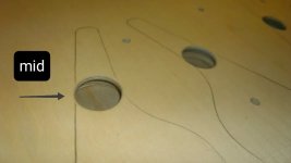
At this point, I'm calling the main section of the horn the "large horn" and the interior the "short horn." Since they switched to using FaitalPRO's HF108 driver for the highs, we can see that its 31 degree exit angle will fill the short horn a few inches from the HF driver. This means that the mids have some space to tap in, but that's going to be crossover-dependent. Here's where I'm a little caught-up. I'm not sure how to properly size the taps for the mids. Are they supposed to be 1/8 of driver Sd? That would put them at 1 & 3/8" for the Beyma 6MCF200Nd, which means they can't tap in until near the end of the horn based on physical size of the hole, which may affect how low the HF can be crossed over to the mids. If I used two holes at half the size, one would be entering the short horn before the other which may cause issues.

The dotted line on the photo above is the 31 degree exit angle of the HF108. The white circle is 11/16" (half of 1 & 3/8"). So if each driver is tapping into each short horn once, then we're golden and I have 1/16" of driver sD that I can place pretty close to the HF entry point for a higher crossover. BUT - since each hole is 1/16 instead of 1/8 sD, does that mean that I'm not getting as many lows through that tap? At some point, I need lows to get down to about 400~600Hz so that they can exit the short horn into the large horn and the 10" lows can take over and properly cross over. Are my mid taps too small to do that correctly? Perhaps slotted taps would work better?
Here's how I got here. 2ftx2ftx4ft box with a 90 degree x 50 degree horn. The horn is 90 degrees, so that means 45 each direction and from the DSL photos, I jumped to the conclusion that they taper off about 2/3 of the way through to add an extra 22.5 degrees at the end of each side. With those dimensions, the interior could only be so deep.
At this point, I'm calling the main section of the horn the "large horn" and the interior the "short horn." Since they switched to using FaitalPRO's HF108 driver for the highs, we can see that its 31 degree exit angle will fill the short horn a few inches from the HF driver. This means that the mids have some space to tap in, but that's going to be crossover-dependent. Here's where I'm a little caught-up. I'm not sure how to properly size the taps for the mids. Are they supposed to be 1/8 of driver Sd? That would put them at 1 & 3/8" for the Beyma 6MCF200Nd, which means they can't tap in until near the end of the horn based on physical size of the hole, which may affect how low the HF can be crossed over to the mids. If I used two holes at half the size, one would be entering the short horn before the other which may cause issues.
The dotted line on the photo above is the 31 degree exit angle of the HF108. The white circle is 11/16" (half of 1 & 3/8"). So if each driver is tapping into each short horn once, then we're golden and I have 1/16" of driver sD that I can place pretty close to the HF entry point for a higher crossover. BUT - since each hole is 1/16 instead of 1/8 sD, does that mean that I'm not getting as many lows through that tap? At some point, I need lows to get down to about 400~600Hz so that they can exit the short horn into the large horn and the 10" lows can take over and properly cross over. Are my mid taps too small to do that correctly? Perhaps slotted taps would work better?
Hi @swiegert2011 . Sorry I've been away for some time as I moved to Switzerland and this is very time consuming!. How is your horn going?
Regarding the taps this is a tradeoff, larger taps result in less compresion at high volume while smaller taps result in less disruption of the HF. Fustruming the taps helps a lot and allows the use of a smaller tap diameter for a given SPL. The 4th order bandpass chamber that the tap and cone cavity form can reduce the maximum operating freqeuncy of the mid but if you use a cone volume filler and fustrum the port this is not going to be the limiting factor. Taps can be simulated in Hornresp easily (offset driver horn) to see how the parameters affect response.
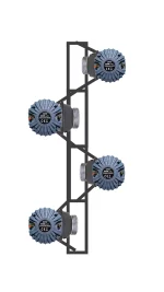
I see one difference between your horn and the danley horns. In the danley horns the drivers are not all in the same plane but are on a curve. See this picture from earlier in the thread of a J8:

Regarding the taps this is a tradeoff, larger taps result in less compresion at high volume while smaller taps result in less disruption of the HF. Fustruming the taps helps a lot and allows the use of a smaller tap diameter for a given SPL. The 4th order bandpass chamber that the tap and cone cavity form can reduce the maximum operating freqeuncy of the mid but if you use a cone volume filler and fustrum the port this is not going to be the limiting factor. Taps can be simulated in Hornresp easily (offset driver horn) to see how the parameters affect response.
I see one difference between your horn and the danley horns. In the danley horns the drivers are not all in the same plane but are on a curve. See this picture from earlier in the thread of a J8:
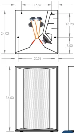
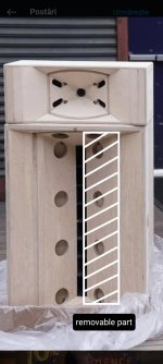
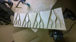
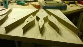
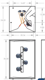
hello friends, this small compact and brilliant model made to build it next year. I thinking and searching but here is the only open topic for J7 so I will upload two models of throats in 4 high drivers no more and improved version for low frequencies. The drawing and dimensions are not calculated and can be adjusted. I hope to understanding and we can succeed together
🫡
🫡
Attachments
-
 IMG_20241207_193937_684.webp139.8 KB · Views: 113
 -
 IMG_20241207_194704.jpg167.8 KB · Views: 106
 -
 IMG_20241125_063039.jpg48.3 KB · Views: 101
 -
 IMG_20241207_202601_940.webp125.1 KB · Views: 113
 -
 img_5_1733253382246.webp33 KB · Views: 96
 -
 img_7_1733253392009.webp31.8 KB · Views: 89
 -
 IMG_20241207_185446.jpg33.3 KB · Views: 98
- Home
- Live Sound
- PA Systems
- Constant curvature tweeter array