Still waiting for someone to show an actual circuit which they hope to 'improve' with a CCS as anode load. Usually NOT a drop in replacement. No point discussing THD, gain, audible effect bla bla if the circuit doesn't work at all 🙂
Take a look at my Chinese EL34 amp thread.
Out of the box it barely produced 2w at over 4.4%. post 47 on the below thread.
After an Ixsys 10M45 replaced the 68k anode resistor, the distortion halved, and with a few other resistor and capacitor changes, it now makes 10w at 1.2% and sounds great drivng the tweeters in my Naim SBL speakers fed from an IXO active crossover.
https://www.diyaudio.com/community/threads/chinese-el34-6sn7gt-se-unusual-topology.401911/page-4
Use of a CCS anode load in triode does not increase output impedance.I'll try a few ideas but pretty sure it is related to the 3rd harmonics going from 30% to 300% of the 2nd.
Maybe due to the increase in output impedance, and/or anode current.
I have not used CCS with a pentode as it does increase output impedance in that case.
The thread subject [asks] "-sonic benefits"
Start with the sound of "One Hand Clapping"
Example:
A driver tube, and a 300B output tube (in a single ended amplifier).
A CCS plate load usually reduces the second harmonic distortion of the driver stage.
That is the sound of "One Hand Clapping"
Now, consider the 2nd stage (the 300B) that also has 2nd harmonic distortion.
Put the driver and the 300B 'together', and you have partial cancellation of the 2nd harmonic distortion
(the driver and 300B 2nd harmonic distortion are in opposite phase, so they partially cancel).
That is the sound of "Two Hands Clapping".
The amount of 2nd harmonic distortion partial cancellation is according to the amount of the driver stage's 2nd harmonic distortion, versus the amount of the 300B's 2nd harmonic distortion.
So, the partial cancellation is different for a driver plate load resistor, than it is for a CCS driver load.
The question is:
Do you want More 2nd harmonic distortion from the amplifier?
Or,
Do you want Less 2nd harmonic distortion from the amplifier?
The "sonic benefit" is up to the Listener.
Just my Opinion
PS
Just inserting a CCS in the plate load, without changing the rest of the circuitry, is not fair to the CCS.
Typically you may not have to change the B+ voltage.
But if you use a high impedance choke as a CCS, you have to Reduce the B+ voltage (otherwise the plate is at a higher voltage than it was with the plate load resistor).
Make the quiescent voltage, current, and bias voltage of the driver tube the same (with a plate load resistor; and with a CCS).
Any other thing than that is not a fair comparison.
And if the necessary circuit change(s) are not done . . . do not even consider doing a double blindfold listening test in order to 'fake the legitimacy' of which is better, plate load resistor or CCS.
Everything is what it seems to be, until you find out it is different!
Last edited:
Original is a pretty yucky circuit. Da old gurus would just use a pentode to drive the EL34 and get your 1.2% 10W without a CCS. Have a look at old Mullard circuits and those from Radio Designers Handbook and its references.Take a look at my Chinese EL34 amp thread.
Out of the box it barely produced 2w at over 4.4%. post 47 on the below thread.
After an Ixsys 10M45 replaced the 68k anode resistor, the distortion halved, and with a few other resistor and capacitor changes, it now makes 10w at 1.2% and sounds great drivng the tweeters in my Naim SBL speakers fed from an IXO active crossover.
https://www.diyaudio.com/community/threads/chinese-el34-6sn7gt-se-unusual-topology.401911/page-4
I think the correct test would be to take one of these old circuits .. already optimised by people who knew what they were doing .. and see if swapping the Anode load for a CCS would be worthwhile. You will probably need to arrange extra bias circuits to get the CCS to work.
I was working with what I had. I didn't want to rebuild something different and also knowing the OPTs were not going to be brilliant. It's only for driving the tweeters in my Naim SBLs so a few watts are enough.
I am about to test a MF X10 clone using a pair of 6N1Ps and then see if it can be improved using a LR8 CCS inplace of the anode resistors. and a higher B+ (upto 90v)
I am about to test a MF X10 clone using a pair of 6N1Ps and then see if it can be improved using a LR8 CCS inplace of the anode resistors. and a higher B+ (upto 90v)
On an unrelated topic, where do you get LR8? They seem to be unobtanium, other than some overpriced ones in e-bay.using a LR8 CCS inplace of the anode resistors. and a higher B+ (upto 90v)
Apologies fir the detour.
I found over a 100, TO92 at TME-UK less than a month ago but just checked and there are none left. (someone on here has probably bought the lot and put them on ebay - wow Littlediode are ripping buyers off - they were about 60p a few weeks ago)
I bought 10 so can spare a couple. PM me if you want them. (wish I'd bought all 100pcs!)
Farenell had some 10m45
I bought 10 so can spare a couple. PM me if you want them. (wish I'd bought all 100pcs!)
Farenell had some 10m45
Last edited:
Got a schematic for MF X10 ?I am about to test a MF X10 clone using a pair of 6N1Ps and then see if it can be improved using a LR8 CCS inplace of the anode resistors. and a higher B+ (upto 90v)
Schematic and more on my thread below.
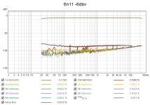
Using a 6N11 instead of 6N1P redcuced the distortion again. (no other changes). A pair of PCC88s are on order. (heater supply will be replaced with a linear adjustable regulator)
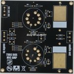
I decided not to try a CCS as the measured performance is acceptable as you can see. This version from ebay seller Wolf does not include any power supply components.
https://www.diyaudio.com/community/threads/x10-clone-tube-buffer-with-6n1p.402747/#post-7439570
Here is the actual X10 schematic: widely found on the 'net. (but mine traced was from the pcb I received which cost £11.99 for the kit excluding the tubes and psu.)
http://myoldvintagehifi.blogspot.com/2010/11/diy-tube-buffer.html


Last edited:
- Home
- Amplifiers
- Tubes / Valves
- Constant current source as anode load-sonic benefits