What are the sonic benefits of using a CCS as an anode load?
I know that a CCS presents a "better" anode load for a tube and that the tube in question becomes more linear,
which should also mean less distortion.
Also the voltage swing should be greater as I understand it.
So, I guess my question is this: -Has anyone built an amp and compared the sonic qualities of a resistor as an anode load
and a CCS as a load?

You need to look at an amplifier as a system. Adding a CCS may, for example, increase total distortion by reducing distortion cancellation between two stages.
Purely on a listening basis I prefer a resistor - to my ears it has a purer sound. I always found something a little unnatural and even a trifle edgy with solid state anode loads. On paper the CCS may have various benefits - I tried them a few times and went back to resistors. I listen mostly to classical, opera and jazz, so timbre of acoustic instruments and voice is absolutely essential. That's my personal choice after various experiments.
I am about to change the 68k anode resistor in my SE Chinese amp's 6SN7 cascode input stage for an Ixys 10M45. I will post the results, both audible and measured in a few days.
I was going to use an LR8 but I think the 10m45 will be more robust.
The current can be adjusted from about 2.4 to 4.4ma with a 500r preset in series with a 680r resistor (its 2.2ma with the 68k resistor)
https://www.diyaudio.com/community/...e-unusual-topology.401911/page-3#post-7419455
I was going to use an LR8 but I think the 10m45 will be more robust.
The current can be adjusted from about 2.4 to 4.4ma with a 500r preset in series with a 680r resistor (its 2.2ma with the 68k resistor)
https://www.diyaudio.com/community/...e-unusual-topology.401911/page-3#post-7419455
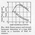
Common triodes, whether voltage or power exhibit lower distortion while driving higher load impedance's.
The D% vs output of a 6A3 is a generic curve & applies to most of these common triodes.
A CCS as a plate load for a voltage amplifier triode does that, the load impedance becomes the following grid resistor
in parallel with whatever internal impedance the CCS achieves.
A mu follower gets us there.
Whether it sounds better depends on each persons ears, how much beer they have consumed & the phase of the Moon,👍
Attachments
Another option is an inductor load. You can have high impedance and low resistance.
Being that a cascode is very similar to a pentode in operation, what is the benefit of having a gigantic impedance as the plate load of a cascode?I am about to change the 68k anode resistor in my SE Chinese amp's 6SN7 cascode input stage for an Ixys 10M45. I will post the results, both audible and measured in a few days.
I was going to use an LR8 but I think the 10m45 will be more robust.
The current can be adjusted from about 2.4 to 4.4ma with a 500r preset in series with a 680r resistor (its 2.2ma with the 68k resistor)
https://www.diyaudio.com/community/...e-unusual-topology.401911/page-3#post-7419455
With the plate load being on the order of 1M ohm or more, that would leave the rp of the pentode/cascode free to be as high as it wants to be. Doesn't that spell bad news for bandwidth?
I understand why a CCS plate load would be a good thing for a triode (flat load line, linearity of the stage becomes equal to linearity of mu), but in a pentode the characteristics are defined by the screen grid, so wouldn't the characteristics of the pentode be more dependent on the supply to the lower triode's grid?
Well, with a tube using a CCS for its plate load, the impedance presented by the CCS will be in parallel with the internal plate resistance (rp) of the tube and the following load resistance.
With a triode, which has low rp compared to the CCS, the result is that the output impedance of the triode stage will be the triode's rp in parallel with the load resistance. Any variation in rp will be apparent to the load. That's all great, because the triode's rp will determine the output impedance, and can be made to be much lower impedance than the load. The triode will be more lightly loaded with a CCS plate load than if it had a resistor plate load. The triode achieves more gain and lower distortion with a CCS plate load.
With a pentode (or a cascoded pair of triodes), which has as high impedance as the CCS, the result is that the output impedance will be very much higher, perhaps more than 10X higher. A typical small signal pentode's rp is about 500k to 1M ohms. The CCS impedance could also be about that (500k to 1M ohms). The following load resistance might be 500k ohms. That means the output impedance could be something like 165k to 300k ohms. If the load has significant shunt capacitance, for instance the Miller capacitance of a fully-bypassed 12AX7 or an RIAA filter network, that high output impedance will be in series with that shunt capacitance, forming a low-pass filter, causing loss of high frequency bandwidth.
With a resistor as the plate load of a pentode, the value of that plate resistor becomes the output impedance of that stage. If we take a 6EJ7 (EF184) and install a 22k ohm plate load resistor, that will be in parallel with the (high) rp of the pentode and with the (should be high) value of load resistance. The result is that the output impedance will be close to the value of the plate load resistor, which is a lot lower in value than the rp of the pentode.
So, my concern is limited to pentodes and cascodes, and has to do with output impedance and how that will affect bandwidth, not with gain and distortion.
Also, keep in mind that the PSRR of a pentode or cascode is many times worse than that of a triode. With a CCS loaded triode the PSRR gets close to the mu of the triode. What does a CCS plate load do for the PSRR of a pentode or cascode?
Last edited:
Well, I'll find out when I try it later in the week. It's very interesting to see whether the results match the predictions and of course, which changes improve the sound given the limitations of the OPTs in a £279 amp.Being that a cascode is very similar to a pentode in operation, what is the benefit of having a gigantic impedance as the plate load of a cascode?
With the plate load being on the order of 1M ohm or more, that would leave the rp of the pentode/cascode free to be as high as it wants to be. Doesn't that spell bad news for bandwidth?
I understand why a CCS plate load would be a good thing for a triode (flat load line, linearity of the stage becomes equal to linearity of mu), but in a pentode the characteristics are defined by the screen grid, so wouldn't the characteristics of the pentode be more dependent on the supply to the lower triode's grid?
I posted my results with a 10m45 in one channel - worthwhile mod it seems.
https://www.diyaudio.com/community/...e-unusual-topology.401911/page-3#post-7419455
https://www.diyaudio.com/community/...e-unusual-topology.401911/page-3#post-7419455
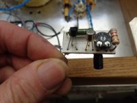
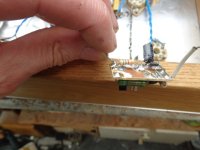
I've tried this a few times with 6SN7's and went back to using a 47k as the anode load, having tried in the past 62k & 100k too but have found a 47k with a HT of 250-300v to be optimum. I found there was no OP gain improvement with a CCS, didn't measure the THD though. I used if I remember right a 2N2907A & MPSA92, the CCS is adjustable like the OP's CCS - see pic.
Andy.
Andy.
Attachments
I've had some great results using CCS as anode load - so much so that I've not played with using cathode CCS in a while.
I've fitted a 10m45 to the other channel of my EL34se amp and have started listening tests.
Strings and brass seem to be more edgy and strident so I amwondering if this is due to the increase in 3rd harmonics.
I need to investigate what has caused this.
Link to my thread in post 13 above.
Strings and brass seem to be more edgy and strident so I amwondering if this is due to the increase in 3rd harmonics.
I need to investigate what has caused this.
Link to my thread in post 13 above.
I will compare that too! I have seen circuits with the ccs loaded with one order of magnitude lower distortion, high gain, basically infinite PS rejection and reduced current draw. I can't see a drawback.
Higher gain, but likely to have lower bandwidth and higher noise.
I'll try a few ideas but pretty sure it is related to the 3rd harmonics going from 30% to 300% of the 2nd.
Maybe due to the increase in output impedance, and/or anode current.
Maybe due to the increase in output impedance, and/or anode current.
Higher noise than what?Higher gain, but likely to have lower bandwidth and higher noise.
- Home
- Amplifiers
- Tubes / Valves
- Constant current source as anode load-sonic benefits