Hi All
I tried CCS for 6SN7 bias but it doesn't work !
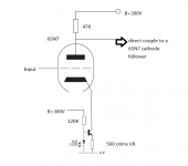
The CCS is as the following drawing and the 150K was replaced by 120K, the BJT is BC550.
Also the fixed resistor 200 ohms was replaced by a 500 ohms VR to trim the bias to 3.5ma for 6SN7.
When I hook up with the power amp., it only gave a very very little sound even the volumn was turned to the end.
I can trim the CCS using the VR to reach at the bias I want, and the plate voltage also varied when the VR changed, everything seems to be OK, but I don't know why it doesn't work 😕
Would any body help me that anything I should pay attention or missing ?
Thanks
Tim
I tried CCS for 6SN7 bias but it doesn't work !
The CCS is as the following drawing and the 150K was replaced by 120K, the BJT is BC550.
Also the fixed resistor 200 ohms was replaced by a 500 ohms VR to trim the bias to 3.5ma for 6SN7.
When I hook up with the power amp., it only gave a very very little sound even the volumn was turned to the end.
I can trim the CCS using the VR to reach at the bias I want, and the plate voltage also varied when the VR changed, everything seems to be OK, but I don't know why it doesn't work 😕
Would any body help me that anything I should pay attention or missing ?
Thanks
Tim
Attachments
Of course this will work-but not for single ended; differential pair or cathode follower only.
Last edited:
Thanks all.
Zen Mod, please see the schematic below.
Piano 3, really? very sorry about that I don't know semiconductor I just learn some of the basic😛
Jerluwoo, you mean the only way to make it work just by pass it and just like Piano 3 said that Constant current sink cannot be applied to SE, please correct me if my understanding is wrong.
Thanks all
Tim
Zen Mod, please see the schematic below.
Piano 3, really? very sorry about that I don't know semiconductor
I just learn some of the basic😛Jerluwoo, you mean the only way to make it work just by pass it and just like Piano 3 said that Constant current sink cannot be applied to SE, please correct me if my understanding is wrong.
Thanks all
Tim
Attachments
With a high impedance in the cathode, your gain will be zero and your output impedance will be sky-high. You will also have some compliance voltage limits.
Strongly recommend that you look over "Valve Amplifiers" 3rd edition to see the right uses and implementations for CCS.
Strongly recommend that you look over "Valve Amplifiers" 3rd edition to see the right uses and implementations for CCS.
It might be best to stick with simple classic circuits (e.g. bypassed cathode resistor) as there is less to go wrong. Once you have gained some experience and understanding you can then move on to fancier ways of doing things.
Thanks all.
Zen Mod, please see the schematic below.
Piano 3, really? very sorry about that I don't know semiconductor
Jerluwoo, you mean the only way to make it work just by pass it and just like Piano 3 said that Constant current sink cannot be applied to SE, please correct me if my understanding is wrong.
Thanks all
Tim
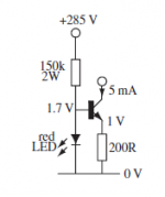
A CCS can be applied to a SE circuit, but you have it in the wrong place. use a PNP transistor rather than the NPN, swap the positions of the LED and bias resistor, stick it in the plate circuit, and use a suitable value of cathode resistor to bias the tube. Alternatively you can use the CCS you have and feed a current mirror in the plate circuit, with the aforementioned suitable bias resistor in the cathode circuit. If you use a CM you can keep it simple or make it fancy with base current compensation or a Wilson mirror. In the case of a SE stage I see no real advantage of the CM over the CCS in the plate circuit. The CM does isolate the CCS from variations caused by swings in plate voltage, but the simple CM is going to be susceptible to variations as well. The Wilson mirror (with or without base current comp) will give a higher plate load impedance.
Or you can stick with a simple resistor like all the classics used 😀
- Status
- Not open for further replies.
- Home
- Amplifiers
- Tubes / Valves
- Constant current sink for 6SN7