What I find complicated with the LM317/TL783 is that you will have current through the pots wiper. Also, for say 12mA, the pot will have to be about 100R. Increasing current to 200mA will decrease pot value to 6R: there will be 200mA running through this 6R, so the 100R pot should be at least a 4W model (0,2A*0,2A*100R)...
another option is a simple IRF820, source (via resistor) to gnd, drain to the tube cathode, and a 9V battery with a (multiturn)pot to set the gate voltage and thereby current.
... and thinking further, with this solution one could use the mosfet gate (or tube grid) to insert some signal in the CCS, to test PS under "dynamic" conditions.
Last edited:
After thinking about this more, I decided to put together a little more concrete list of requirements. This might be a bit overly ambitious but it's better to aim high and miss, I think. I also put these as an edit to the initial post.
Must Haves:
- Voltage range: 100V-400V
- Current range: 5-75mA
- Max Power: 30W
- Maximum of two range switches (hi/lo current and hi/lo voltage)
Nice-to-haves:
- Completely self-powered (battery bias supply acceptable)
- Single knob adjustment for full Voltage/Current range
- Junkbox build friendly
In the Valve Wizard link I gave he powers the CCS from B+.
Yes he does, and that link provides a good overview of different strategies. However, unless I'm mistaken, none of the proposed circuits will sink constant current across a wide range of B+ voltages (see revised requirements). The triode circuit will drift since it is's bias is a voltage divider. and the load resistors for the LED/zener circuits will eventually over/under drive the diodes. Additionally, those bias LEDs are sinking current themselves which increases the minimum current load making the 5mA lower limit harder and harder to hit.
This is a good idea: valves can dissipate a lot of heat in little space (due to higher allowable delta T in comparison to SS on heatsinks).
What I would add is that instead of the LM317 one could also apply a voltage multiplier (quadruplier) to the filament voltage and generate a negative voltage from that. This can then be applied to a pot, with wiper to G1: changing pot settings changes current through the tube. Add a 10R or so resistor in series with the cathode to measure the current through the tube.
Ideally this load to be self-powered from just the B+ so I won't have a filament voltage handy. A suitable isolated DC-DC buck converter could be used but I'm not sure one could be sourced economically that would also handle the intended voltage range.
What I find complicated with the LM317/TL783 is that you will have current through the pots wiper. Also, for say 12mA, the pot will have to be about 100R. Increasing current to 200mA will decrease pot value to 6R: there will be 200mA running through this 6R, so the 100R pot should be at least a 4W model (0,2A*0,2A*100R)...
Good point on the current through the sense resistor, I hadn't done that math yet. If you are content with a smaller current range (5-75mA) your Rsense range is 16-250 which you could split between a 16ohm resistor and a 250ohm pot in series. In that configuration the fixed resistor does all the heavy lifting so you can use a junkbox pot without any trouble (assuming you have a 250R pot laying around, that is).
An idea that comes to mind is as said battery bias. Then a number of MPSA ( KSP etc ) 44 and 94 transistors. Each has it's own emitter resistors to share the load. Switch off resistors for lighter loads. Many surface mount transistors offer high power dissipation if PCB layout is followed from the data sheet. They might offer 500 V into the bargain. Here are a coupled picked for price.
PBHV9050T | NXP PBHV9050T PNP High Voltage Bipolar Transistor, 0.15 A, 500 V, 3-Pin SOT-23 | NXP
PBHV8540Z | NXP PBHV8540Z NPN High Voltage Bipolar Transistor, 0.5 A, 500 V SOT-223 | NXP
As the devices won't have high gain battery life may be a factor.
PBHV9050T | NXP PBHV9050T PNP High Voltage Bipolar Transistor, 0.15 A, 500 V, 3-Pin SOT-23 | NXP
PBHV8540Z | NXP PBHV8540Z NPN High Voltage Bipolar Transistor, 0.5 A, 500 V SOT-223 | NXP
As the devices won't have high gain battery life may be a factor.

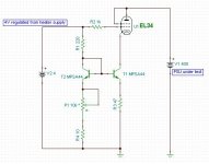
Here is an idea so simple it must be bad. Never tried it so very easilly will be told no way. The idea is to make a current mirror. Choose whatever degeneration resistors that best suit. We might loose 200 mV or even 1 V through these resistors, the red one is the showing the current of the load ( collector ). As we need to calibrate the device even the cheapest 1N4007 version should be OK. The third version is the one that might offer nearer to calculated results. It's hard to say if these circuits are the best use of parts. I suspect Andrew T might have some ideas on this. The circuit needs PNP for the other end ( B+ ).
It could be as simple as this: EDIT: Oh, you don't want a heater supply to be involed. Nevermind.
Attachments
Last edited:
KISS
Use a large N-FET such as the STW11NM80. Mount it on a suitable heat sink with appropriate isolation/insulation material (safety).
Stick a current meter from Source to ground.
Put a 100K resistor from drain to the top of a 10K pot.
Connect the bottom of the pot to ground.
Connect the wiper of the pot to the gate of the FET via 220R resistor. Place a 1Meg resistor from the wiper to ground for security.
Ta-Da. Adjustable load for your PS.
I think if a shunt resistor ( to 0 V ) is added to the LM317 CCS any current you want is possible as a reference current for the current mirror ( No45 CCS ). It is then up to the design of the current mirror how well it can clone that current. This way the test set could do 1 mA or less. Even if the circuit isn't perfect I imagine once measured it will give the same results each time. One would hope temperature drift would be equal in all devices. A test in the fridge and the boiler cupboard.I have a hunch it would be more or less the same from 8 to 40 C .

If using a low beta device like BU508 the mirror balance might be 30 % out. The 508 is cheap and likely to work OK on a heat sink. BUX 85G is a high gain device related to other choices and very cheap at RS components. It will just do 30 watts if the heat sink can keep the case temperature down to 75C. I doubt that will be easy. If a number of BUX 85G were used it could work. Lets say 3 and 120R for each ( red ).Just paralell all the devices. This still has a better beta than BU508. On the other hand BU508 is a 700 Volt device.
As long as the errors are constant with temperature and time I don't think they matter. KISS. The only thing that matters is the red resistor is measured. The value of that resistor can be reduced. I would exspect greater drift if so. The purple resistor is dependant on Vbe of the BD140 or whatever. BD140 is just about OK at 1 watt in free air. I am assuming a 9 to 12 V battery.
Where I think people will get confused is this current mirror would be a waste of time in the circuits usually using a current mirror. Here it is a means to an end and the errors are understood. I see no good reason to use LM317 except to say it might nail the current better. A LED could be used in place of the 2 x 1N4007. The purple resistor changed to suit. 1.6 -0.6 = 1 V 1/75 mA = 13 R . The LED might be better or worse. It's hard to say. The advantage of the diodes is they should have a similar temperture coefficient as all the other silicon devices. A LED by it's nature is nearer to a band gap reference. I would go for 1N4007 myself and keep all devices near the heat sink. Now I hope someone will build this and see where it goes wrong. It might have to be me. As I don't have 450 VDC to hand it's playing with 320 VDC of the mains electricity rectified. I have 280 VAC so can get to about 385 VDC perhaps.
The 3V ??? is how low it could be pushed at a guess using 39R, I really have no idea. At 1 mA to 5 mA it should be inside the range of small triodes like ECC82 when the cathode. If testing the anode end of things I would use a PNP output type with NPN CCS. In some circuits the high collector impedance is an advantage. Although doubtless less good than a simple CCS ( See Morgan Jones ) it might show distortion advantages over a resistor. M J uses a cascode CCS to get a near infinite impedance for the anode to see. Very simple and near perfect linearity within what's possible. Very cheap also. It is arguable that set up as he does the cascode CCS is like a pure resistance fed from a near infinite voltage with defined current. Thus the curve of the pentode or whatever is made nearly a line. As valves are mostly class A the Ft of 6 MHz isn't a problem. M J looks to Early effect in his cascode. If not doing it his way some extra 2 nd harmonic might result. Hardy a disaster if so. I think not using bipolar devices in valve/tube circuits might be to misunderstand. It is arguable that bipolar linearty as CCS is the best linearity we might have when needing this. MOS FET and valves not really as good. I would exspect valve qualities to be more obvious when using a bipolar andode load. For the cathode the resistor is King, it is the more sophisticated sollution. No harm finding it with a CCS.
Last edited:
- Status
- Not open for further replies.
- Home
- Amplifiers
- Power Supplies
- Constant current load for testing power supplies