I'd use a CCS load cell (electronic load ) using a power HV MOSFET and a op-amp. 20W should be very simple. I think 400V is very common and 1000V devices aren't too rare. then you don't need complex negative bias AFAIK you could use a 9V battery
I hate incandescent light bulb loads (they tend to be max current into overload at startup)
I hate incandescent light bulb loads (they tend to be max current into overload at startup)
I'd use a CCS load cell (electronic load ) using a power HV MOSFET and a op-amp.
The more I dig into this the more I think this is the correct answer. What is the crowd-favorite around here for HV MOSFETs (or general purpose opamps for that matter)? If there are any with broad application as CCS, drivers, Phase inverters, etc. I'll probably grab a handful.
The CCS that I mentioned at the start of this thread uses a high voltage MOSFET and a TL431 to drive the gate and set the current. Simple and reliable. See TL431 data sheet for examples.
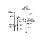
I have been using this for a long time as LTP tail. Very reliable! It could be adjusted to your needs for the mosfet bias and load. Mosfet runs very hot but it doesn't care! Heatsink is required of course. Also the backplate is at the load's voltage (155V in the particular circuit)
Attachments
What about a higher voltage mosFET?
Dial up the dissipation by adjusting the gate voltage (with reference to the source).
Use a gate resistor, 100r?, to prevent oscillation.
Add extra mosFETs for higher power.
Dial up the dissipation by adjusting the gate voltage (with reference to the source).
Use a gate resistor, 100r?, to prevent oscillation.
Add extra mosFETs for higher power.
Id aim for using a 9V battery to power everything. E.g. look for lower Iq devices .
An dual opamp and Vref device, most common stuff is 3mA / amp so yer looking at ~10mA total or better total using junkbox parts.
A power HV MOSFET youll want a ~100W device at least and >400V so pick a package you like to match a 20-40W heat sink. something biggish so you don't have to power a 9V fan.
EEVblogger talks https://www.youtube.com/watch?v=8xX2SVcItOA
(off-topic - sorry)
That's not a characterisation - it's a grossly inaccurate generalisation (and a mis-spelling).soccer houligans?
If wanting a cheap high power 32R, 16R and 8R load a generic Bosch 1700 watt Half Moon element is very cheap. It is two sections joined so makes for easy connection. Whilst it might not be an exact 8R it will serve well enough for testing. £10 will buy one. I am almost certain I measured one and found it more or less 32R.
What precautions will I need to take w/r/t insulating the MOSFET from the heatsink here? If I understand the tab will be at full HT potential. Will a silicon pad and a shoulder washer (with non-conducting paste, of course) be sufficient?
If you ask about schematic in post #24, I' ve mounted the whole heatsink on a wood surface so it is floated from the metal chassis. The mosfet is straight attached to the heatsink. Not the best implementation but the heatsink is well hiden inside the chassis and I preffered to have the best thermal contact. In my application the mosfet really runs hot as hell...Anyway, if someone who knows better could suggest a proper insulation, I would be interested too!
Grab an EL34 or other pentode/tetrode, put an lm317 in its cathode with a variable set resistor, and tie the grid to ground. Works with older oddball TV or radio tubes of the appropriate voltage too.
What precautions will I need to take w/r/t insulating the MOSFET from the heatsink here? If I understand the tab will be at full HT potential. Will a silicon pad and a shoulder washer (with non-conducting paste, of course) be sufficient?
that should be fine, use the normal creepages and clearances as used on your powersupply. ~4 mm
me Id investigate building the thing in its own well ventilated enclosure and run everything floating Re no other wires ( note > any disconnected energized test leads should always be covered , right.)
*any other plugged in test gear will provide SE grounds on yer testing.
Last edited:
Grab an EL34 or other pentode/tetrode, put an lm317 in its cathode with a variable set resistor, and tie the grid to ground. Works with older oddball TV or radio tubes of the appropriate voltage too.
A very elegant solution. Thank you.
However the 40V Vmax of the LM317 will not allow you to cut-off the tube sufficiently to reach the lower-end of the current range for many tubes and plate voltages. Plus, even if it did the LM317 has a required minimum load of 10mA.
You could add a battery between ground and the grid to give you a leg-up. A pair of 9V in series will let you get the grid to ca. -58V which should be enough to get down to 10mA or less . You could even switch it if you need more than 40V of total adjustment to reach the whole current range.
But that still leaves the lower limit at 10mA. Enter the LM334 which provides adjustable CCS operation from 1uA and 10mA. Putting a Hi/Lo switch at the cathode to toggle between the LM317 and the LM334 will give you adjustable current down as low as your bias allows and as high as your max plate dissipation will permit.
Some manufacturers specify the minimum current as 5mA.A very elegant solution. Thank you.
However the 40V Vmax of the LM317 will not allow you to cut-off the tube sufficiently to reach the lower-end of the current range for many tubes and plate voltages. Plus, even if it did the LM317 has a required minimum load of 10mA.
You could add a battery between ground and the grid to give you a leg-up. A pair of 9V in series will let you get the grid to ca. -58V which should be enough to get down to 10mA or less . You could even switch it if you need more than 40V of total adjustment to reach the whole current range.
But that still leaves the lower limit at 10mA. Enter the LM334 which provides adjustable CCS operation from 1uA and 10mA. Putting a Hi/Lo switch at the cathode to toggle between the LM317 and the LM334 will give you adjustable current down as low as your bias allows and as high as your max plate dissipation will permit.
Does that minimum apply when in constant current mode?
If 1.25V is maintained across the output resistor, then it is still operating as a CCS.
Any reason why a power transistor CCS can not be used ? 2SC5200 comes to mind, a 250 V device. I have never tried one at 1 mA. I suspect it would work. If wanting less second harmonic distortion you might need a slightly greater reference voltage than a typical CCS ( Early effect ? ). Use 3 biasing diodes ( or LED ). The voltage loss is more or less that of the LM317 or better. When I did this the linearity was at least as good as the LM317. I used BD139 with excellent results. Valves were EL37/34/KT88. All settle at about 30 to 40 VDC and 60 to 80 mA.
The Valve Wizard
The Valve Wizard
Any reason why a power transistor CCS can not be used ? 2SC5200 comes to mind, a 250 V device.
LM317HV exists if it helps.
http://www.ti.com/lit/ds/snvs773d/snvs773d.pdf
Biggest reason I haven't looked at using a power transistor or the LM317HV is that I don't have any in my inventory. Beyond that, another strike against the LM317HV is that it is 5x the price of the normal part (and only gets you from 40V to 60V). As for the discrete transistor approach I have not found (in my brief searches at least) a discrete CCS design that will cope well with the intended B+ swing while still being self-powered.
In the Valve Wizard link I gave he powers the CCS from B+. I did this also as I had a CCS using a PNP device on the previous stage which was also the pentode g2 supply. 3 birds with one stone. It had filtering for the g2. Two LED's two resistors and a capacitor for 3 uses. The final bird was the KT 88 current sink ( NPN, looks the same as a current source ). I did this to know what my valves were able to do. The circuits were replaced by resistors when I had my data. Being that the CCS exploits the best performance of bipolar devices they would not have harmed the sound quality. One fact that is often ignored is that the cathode resistor is the most sophisticated way of opperating the valve.
There is a very simple depletion FET idea that works something like valve biasing when a CCS. This is as simple as the LM317 idea. As I don't know of a device to recomend I will pass it to another. I think I read of silicon carbide FET's of this type. Alas expensive no doubt. ( Item 3 in 2 nd link shows how ). Depletion is like valves in how they are biased ( J FET's as a rule also ). Most MOS FET's and bipolar transistors are enhancement types and need a bias supply. There are JFET's as two terminal ready made CCS. 100 V 5.6 mA is about as big as they get. A number can be used together.
The last link is worth a read.
https://www.rapidonline.com/atc-semitec-e-452-e-562-current-limiting-diode-crd-4-5ma-47-2608
circuit design - Typical use of depletion MOSFET - Electrical Engineering Stack Exchange
https://en.wikipedia.org/wiki/Cathode_bias
http://www.diyaudio.com/forums/tube...-mosfet-cascoded-constant-current-source.html
http://uk.farnell.com/microchip/lnd150n3-g/mosfet-n-ch-500v-0-03a-to-92-3/dp/2450521
Last edited:
Grab an EL34 or other pentode/tetrode, put an lm317 in its cathode with a variable set resistor, and tie the grid to ground. Works with older oddball TV or radio tubes of the appropriate voltage too.
This is a good idea: valves can dissipate a lot of heat in little space (due to higher allowable delta T in comparison to SS on heatsinks).
What I would add is that instead of the LM317 one could also apply a voltage multiplier (quadruplier) to the filament voltage and generate a negative voltage from that. This can then be applied to a pot, with wiper to G1: changing pot settings changes current through the tube. Add a 10R or so resistor in series with the cathode to measure the current through the tube.
I would look into a GU50 with 12,6V heater: quadruplier on that generates about -60V bias which should be plenty to control current over a wide range. And 12VAC trafos are very common.
Edit...hmm, looking at triode curves for the GU50, the -60V will not work for very high plate voltages @ low currents (say 500V at 10mA will requires about -120VDC at G1).
Last edited:
LM317HV exists if it helps.
http://www.ti.com/lit/ds/snvs773d/snvs773d.pdf
TL738. 125V, 700mA
http://www.ti.com/lit/ds/symlink/tl783.pdf
Minimum load is quoted as 15mA, but if you're going that low then presumably you'd just use power resistors to test the supply. (These ICs still regulate 'well enough' below their minimum current that I doubt this is a real handicap in this application.)
Last edited:
- Status
- Not open for further replies.
- Home
- Amplifiers
- Power Supplies
- Constant current load for testing power supplies