Has anyone built & tried Rod Elliott's "Constant Collector Current hFE Tester for Transistors"?
Project 177
His comment:
"The advantage of testing with a constant (or nearly constant) collector current is that each device you test is subjected to the same heating effect, so, at least in theory, the results will be more predictable (or perhaps less unpredictable)."
Project 177
His comment:
"The advantage of testing with a constant (or nearly constant) collector current is that each device you test is subjected to the same heating effect, so, at least in theory, the results will be more predictable (or perhaps less unpredictable)."
Of course that comment assume all the devices have the same die area, which isn't usually true. Using low duty cycle pulses is the best way to reduce self-heating effects, but its more complex.
Its a nice simple approach, but you have the issue of having to do division to get the actual beta value - adding a microcontroller to measure the base shunt voltage and do the calculation would be a handy extension, and would allow pulse testing too.
Figure 5 should be taken with a pinch of salt BTW (ie spot the error!)
Of course that comment assume all the devices have the same die area, which isn't usually true. Using low duty cycle pulses is the best way to reduce self-heating effects, but its more complex.
Its a nice simple approach, but you have the issue of having to do division to get the actual beta value - adding a microcontroller to measure the base shunt voltage and do the calculation would be a handy extension, and would allow pulse testing too.
Figure 5 should be taken with a pinch of salt BTW (ie spot the error!)
+/- 12V magically become +/- 6V. There should also be a cap from the artificial ground to the +12V or +6V rail, which ever is supposed to be correct.
OK, I'll bite----what's the error?Figure 5 should be taken with a pinch of salt BTW (ie spot the error!)
IIRC, the great French author H. Schreiber described such a test set about 40 years ago in the "Le Haut-Parleur" magazine.
I wasn't able to find it on the net, yet it must be there since this title is archived, in American Radio History and elsewhere.
With some patience and the correct search terms, it should be possible to locate it.
That said, there are many possible answers: I have brewed my very own, also a long time ago, but it would be impossible to describe here, because it is a complete lab instrument, thus pretty complex (and in paper form).
It is probably possible to come up with a simple yet usable alternative. I'll think about it, and may have an illumination...
Obviously, the +/-12 is a single 12 volt floating supply (as shown in figure 4). This is labeled 12V+ and 12V-. So the 12 volts is split into two 6 volts supplies. These outputs are labeled +6V and -6V.. I agree the labeling could be a bit more clear, but it is not really 'wrong'.
Last edited:
Yes, the recommendation of a single 12V or 2 x 5V switchmode power supplies is the key to the intention. It would have been better to specify that on the diagram but it's 2 years on and a bit late to simply edit without some explanation.
It is probably possible to come up with a simple yet usable alternative. I'll think about it, and may have an illumination...
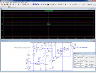
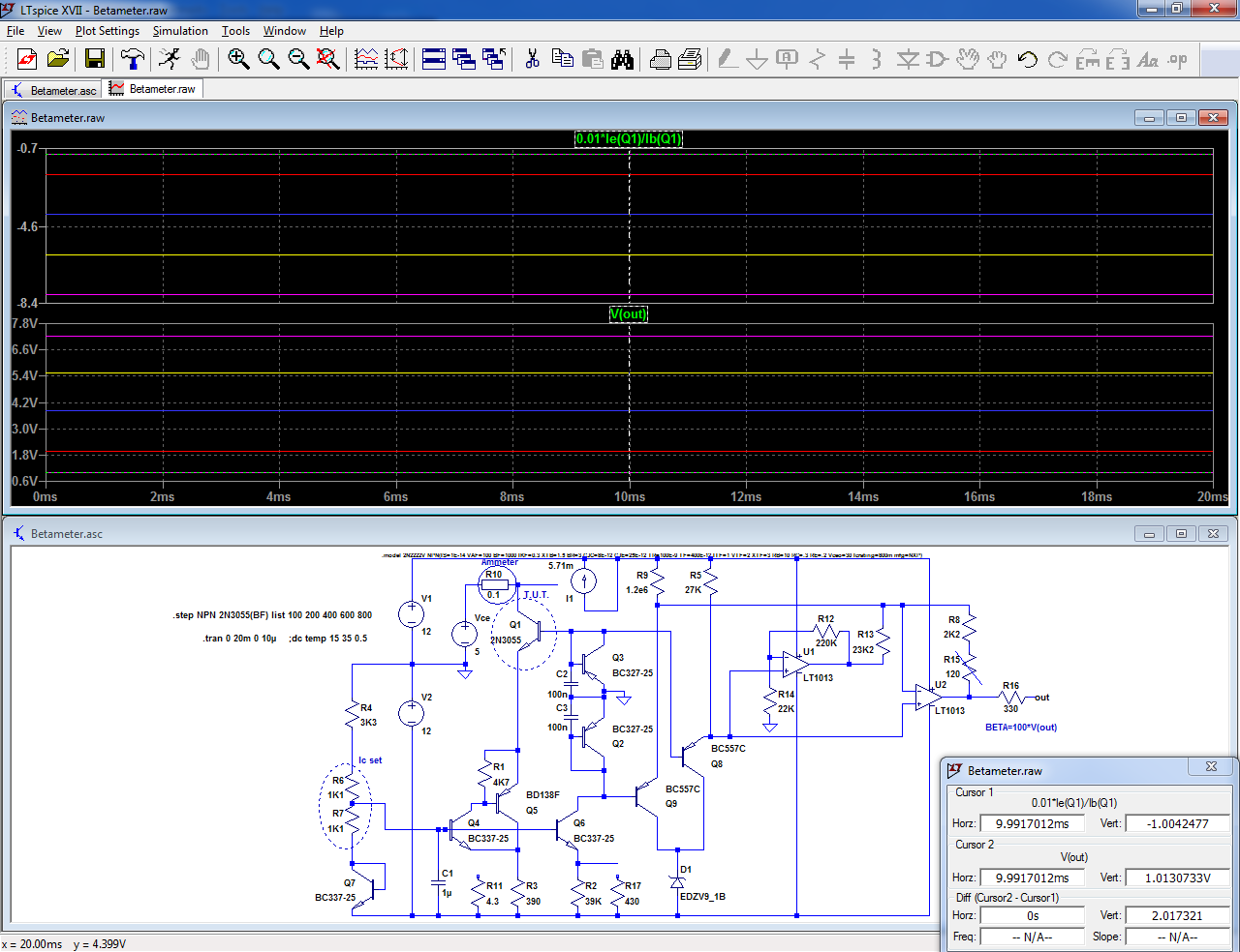
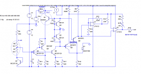
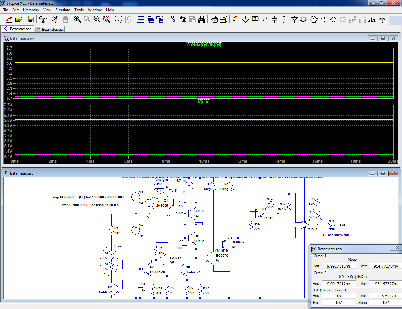
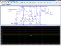
Here is a first, basic draft for a constant-current, direct-reading β-meter:
Of course, it is somewhat simplified and does not include higher order corrections, but that is a start, and if it works as intended it would be perfectly usable, especially for comparisons.
With the values indicated, this example covers an Ic of ~0 to 100mA (with a 2K2 potentiometer), and the β value is a voltage = to 1V for β=100.
A multimeter or panel-meter could be connected to the output.
The Vce source is shown as independent, but it could be the main 12V too.
Other values or range-switching would be possible too.
The sim shows a 2N3055 tested, with its β value stepped between 50 and 800.
The graph does not show the exact spice value, because the actual value depends on a number of correction factors.
The actual β value is displayed in the other pane, and shows a very good agreement.
I will refine the circuit and make some breadboard tests.
Attachments
Elvee, I'm sure that is an excellent design, but WAY too complicated! I much prefer your simple efforts, like your BRILLIANT de-noiser!
No problem, I understand perfectly: it makes no sense to build a dedicated instrument if you only need to measure a dozen of transistors or so.
It is much simpler to improvise a setup with a supply or two, some multimeters, and make the calculations by hand.
I will however pursue the project: I am sure that some people will find it useful
It is much simpler to improvise a setup with a supply or two, some multimeters, and make the calculations by hand.
I will however pursue the project: I am sure that some people will find it useful
To change this sim into a real tester, two problems need to be addressed: one is the polarity switching, and the other is the Ic range.
In its current form, NPN only with a single 0-100mA range, it is a good starting point for a general -purpose tester, but it is somewhat limited.
Changing the collector current range looks relatively easy: one just has to adapt the CCS's defining the collector and reference currents.
However, the design is heavily simplified, and built around the 100mA range. If this current is significantly modified, the simplified CCS's, informal log and antilog converters will lose some of their accuracy.
Of course, it is always possible to use massive feedback, with opamps everywhere but the spirit of the project is based on simplicity and minimalism.
The only opamps used so far are the final stage of the antilog converter and an (optional) logarithmic CM canceller, and ideally it should stay that way.
Fortunately, the circuit tolerates one decade above and below 100mA, with a reasonable loss of accuracy:
Attachments

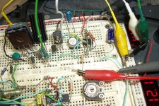
I have made a reality check:

The circuit worked broadly as expected, but to arrive at a reasonable accuracy, I had to refine some aspects, related mainly to matching/thermal tracking.
I had expected it, but I wanted to have a real physical feel of it to make mods.
Q2/Q3 and Q8/Q9 need to be closely matched, and they have to track thermally, which is not obvious because they are subjected to differences in dissipation.
In the sim, there is no such problem of course: transistors are ideally matched, and kept at exactly the same temperature.
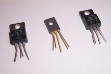
In reality, I have selected two BD131 for Q2/Q3, and bolted them together with their mounting base in contact to ensure a very good thermal contact.
The two TO126 cases are substantial, to cope with the wide variation of dissipation depending on the range and the beta of the DUT.
For Q8/Q9, I could use the easy option: a dual transistor, but I had to reduce their Vce with a different diode arrangement.
The 9.1V zener left ~3V of Vce, which was too much, and not very accurate because of the subtraction.
Now, the Vce is approximately 1Vbe. The reference diode is a zener too, because it is not gold-doped unlike common signal diodes and thus allows a slightly larger voltage. The likes of OA200 aren't easily available anymore.
U2 needs to have a low offset, preferably <0.2mV
The circuit worked broadly as expected, but to arrive at a reasonable accuracy, I had to refine some aspects, related mainly to matching/thermal tracking.
I had expected it, but I wanted to have a real physical feel of it to make mods.
Q2/Q3 and Q8/Q9 need to be closely matched, and they have to track thermally, which is not obvious because they are subjected to differences in dissipation.
In the sim, there is no such problem of course: transistors are ideally matched, and kept at exactly the same temperature.
In reality, I have selected two BD131 for Q2/Q3, and bolted them together with their mounting base in contact to ensure a very good thermal contact.
The two TO126 cases are substantial, to cope with the wide variation of dissipation depending on the range and the beta of the DUT.
For Q8/Q9, I could use the easy option: a dual transistor, but I had to reduce their Vce with a different diode arrangement.
The 9.1V zener left ~3V of Vce, which was too much, and not very accurate because of the subtraction.
Now, the Vce is approximately 1Vbe. The reference diode is a zener too, because it is not gold-doped unlike common signal diodes and thus allows a slightly larger voltage. The likes of OA200 aren't easily available anymore.
U2 needs to have a low offset, preferably <0.2mV
Attachments
Further rationalization:
For the low-current range (0 ~ 10mA), the base current from Q8/Q9 began to become non-negligible compared to the current provided by Q1/Q6, causing additional errors.
This did not compromise the usability, but it degraded the absolute accuracy.
.
An obvious solution is to reduce the operating current of Q8/Q9, but I was reluctant to do it, because I prefered to operate all the transistors involved in the analog computing at broadly comparable currents, to reduce higher order effects.
As there was a compelling reason, I did try it in the end: I first increased the impedance level tenfold, and noticed no adverse effect.
As a result, I also tried a 100x fold increase... and it also worked without any problem.
Increasing the impedance has the advantage of reducing parasitic currents, but it also eliminates self-heating issues.
Thus, my initial fears were unfounded, at least for this range of currents.
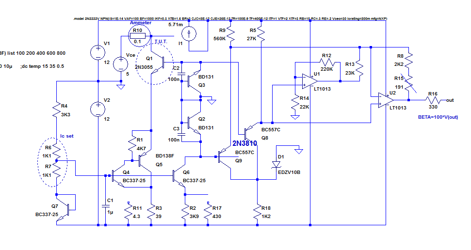
This is the circuit I tested (in reality, on the breadboard prototype):
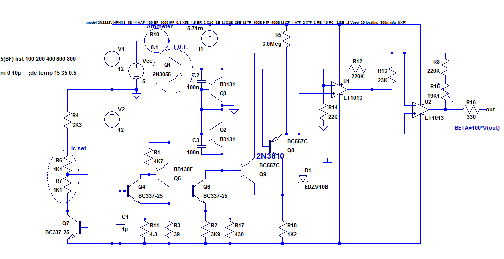
For the final version, I am probably not going to be that extreme: a 30x increase is probably more than sufficient, and will be less sensitive to stray fields.
I tested the new version with "extreme" transistors: superbeta transistors from Sanken having up to 1K of β, and a BD131 reject having <50 β:
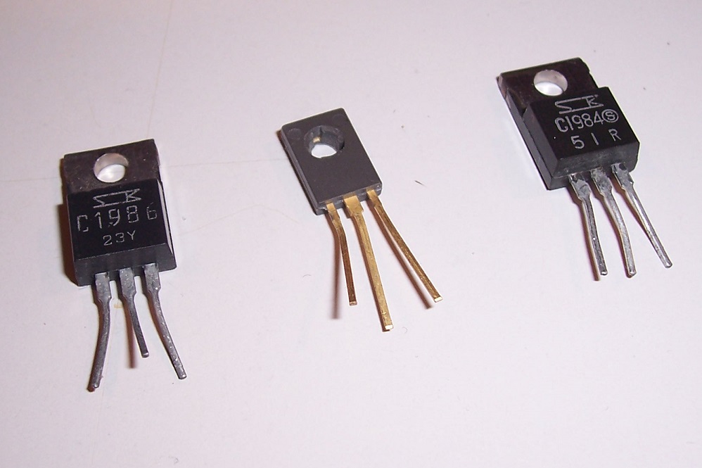
The test succeeded perfectly, meaning the current reduction can be safely implemented
For the low-current range (0 ~ 10mA), the base current from Q8/Q9 began to become non-negligible compared to the current provided by Q1/Q6, causing additional errors.
This did not compromise the usability, but it degraded the absolute accuracy.
.
An obvious solution is to reduce the operating current of Q8/Q9, but I was reluctant to do it, because I prefered to operate all the transistors involved in the analog computing at broadly comparable currents, to reduce higher order effects.
As there was a compelling reason, I did try it in the end: I first increased the impedance level tenfold, and noticed no adverse effect.
As a result, I also tried a 100x fold increase... and it also worked without any problem.
Increasing the impedance has the advantage of reducing parasitic currents, but it also eliminates self-heating issues.
Thus, my initial fears were unfounded, at least for this range of currents.
This is the circuit I tested (in reality, on the breadboard prototype):
For the final version, I am probably not going to be that extreme: a 30x increase is probably more than sufficient, and will be less sensitive to stray fields.
I tested the new version with "extreme" transistors: superbeta transistors from Sanken having up to 1K of β, and a BD131 reject having <50 β:
The test succeeded perfectly, meaning the current reduction can be safely implemented
Attachments
This is the provisionally final version, using sensible resistor values:
The reduced Vce arrangement of the antilog transistors has been scrapped, since it's not required anymore.
Two important problems remain to be addressed: the calibrability, and the polarity switching
The reduced Vce arrangement of the antilog transistors has been scrapped, since it's not required anymore.
Two important problems remain to be addressed: the calibrability, and the polarity switching
Attachments
Polarity is a recurrent problem with transistor testers. Tube testers have other types of complication, but at least they are exempt from this type of conundrum.
There are a number of methods to deal with the two sexes: one is to switch everything, to reuse as much as possible of the active circuits.
It is the "historic" method, because switches were cheap, but transistors and active devices were expensive.
Another method is to simply duplicate the circuits, with all the polarities reversed. Practically no switching is involved, but it is part-intensive.
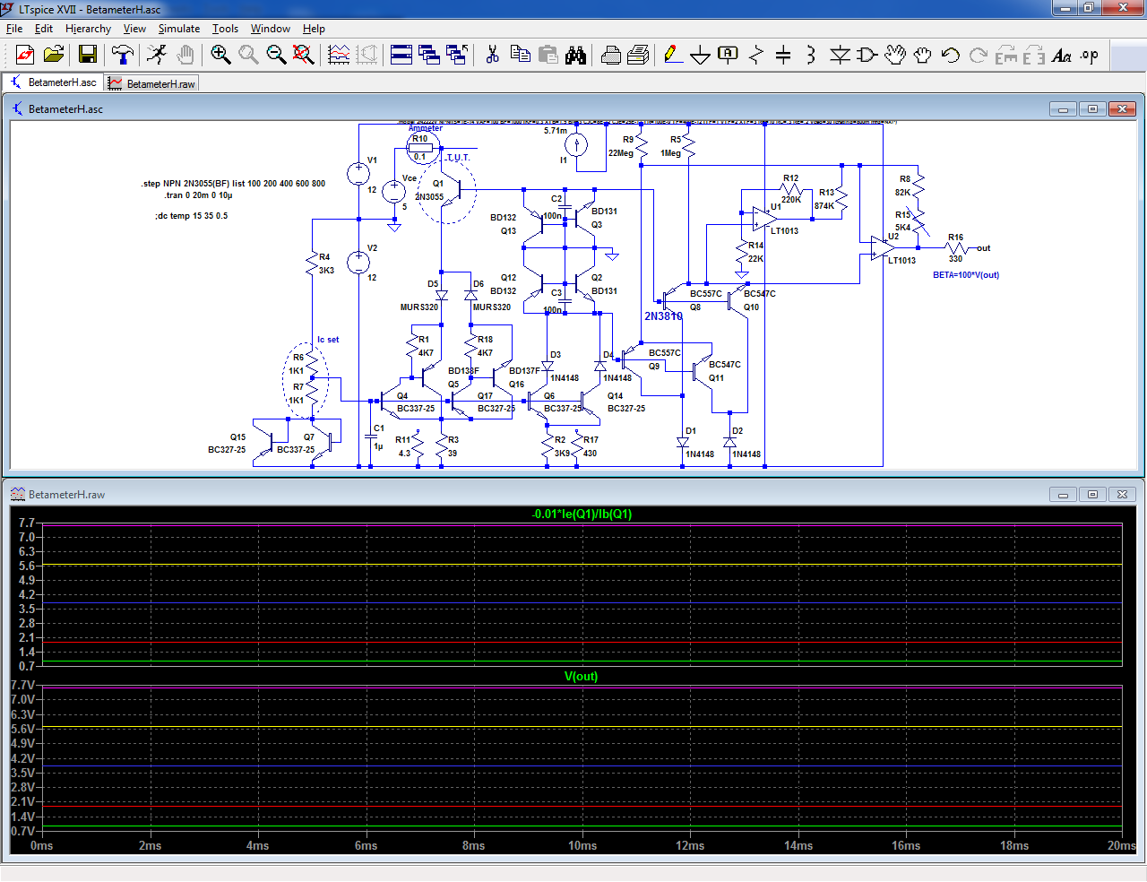
A middle-term is an "hermaphrodite" circuit, that works equally well with all polarities reversed: that's what I opted for here.
Basically, all the functions blocks are duplicated, but the processing, indication and range-switching are common, which minimizes drastically the number of contacts required.
It is a reasonable tradeoff for modern circuits.
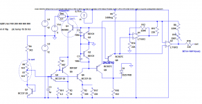
This is the adapted circuit and its sim, showing that the operation for the unisex variant remains exactly the same. There are blocking diodes, of course:
This circuit could therefore serve as a flagship for the LGBT cause!
In practice, the β-acquisition would have a polarity inverter, but the subsequent opamp circuits would remain the same.
The polarity on the indicator would be reversed, but this is in line with the presentation of semiconductor data, so it should be alright
There are a number of methods to deal with the two sexes: one is to switch everything, to reuse as much as possible of the active circuits.
It is the "historic" method, because switches were cheap, but transistors and active devices were expensive.
Another method is to simply duplicate the circuits, with all the polarities reversed. Practically no switching is involved, but it is part-intensive.
A middle-term is an "hermaphrodite" circuit, that works equally well with all polarities reversed: that's what I opted for here.
Basically, all the functions blocks are duplicated, but the processing, indication and range-switching are common, which minimizes drastically the number of contacts required.
It is a reasonable tradeoff for modern circuits.
This is the adapted circuit and its sim, showing that the operation for the unisex variant remains exactly the same. There are blocking diodes, of course:
This circuit could therefore serve as a flagship for the LGBT cause!
🏳️*🌈
In practice, the β-acquisition would have a polarity inverter, but the subsequent opamp circuits would remain the same.
The polarity on the indicator would be reversed, but this is in line with the presentation of semiconductor data, so it should be alright
Attachments
I have posted the final version of the tester in a dedicated thread:
A constant-Ic β-tester: β-Master 🌈
A constant-Ic β-tester: β-Master 🌈
- Home
- Amplifiers
- Solid State
- Constant Collector Current hFE Tester for Transistors