Did you monitor the variac output voltage and set it to be identical to the raw mains value. Most variacs give a higher output voltage on maximum e.g a range of 0 to 110% of the incoming supply.
Would disconnecting the transformer secondary center tap from earth ground cause instabilities in any way? Would be interesting to try.. or should I try a choke or some fancy ferrites? I assume disconnecting ground would be pretty non-compliant..
Or is an external filter the only way to go?
Or is an external filter the only way to go?
You said -quote-"neutral and ground aren't necessarily the same in my area".
In the UK the actual mains neutral returns to the power station where it is grounded but household etc have a earthed ground connection locally .
Using an ELT ( digital loop tester ) for safety reasons the earth return should be a very low value .
I have a quality Megger and even on a long extension led to my computer (PC) its ONE ohm which is not perfect but livable , its less than that in a wall connection .
Like any other piece of electrical wire it can act as an aerial especially if it presents a "high " impedance " which isn't the same as a a high impedance at an amplifier input so we are talking very low ohmage resistance .
You will see in one of my links how this interference can travel round a transformer secondary .
If your mains earth is of a high value then provide a temporary--LOCAL --earth -- long steel spike in the ground to about 5 feet just to try it wrap round copper wire and use that as mains "earth " water round it well .
Of course if you live in a flat ------
Well you could try ferrite rings etc but if your local earth is okay then that leaves complete isolation , you are halfway there finding out it travels via the earth.
As its a minority that has this type of trouble on your make then other people don't have the mains interference problems you do but it is a very sensitive design .
This all depends on whether your amplifier design is earth referenced
Thank you very much for all the invaluable information! I've learned a lot by looking at your links, reading up on ferrite composition, wiring etc.
However, what exactly about this amp that makes it more sensitive than others? And when you say earth referenced design -- when return/neutral and earth is tied together, isn't that the same as earth referenced?
If I were to add a choke on the earth wire, would I risk end up altering the sound of the amplifier? And in what way?
I obviously have a lot to learn about the apparently simple concept of impedance. Your comments help tremendously in remedying this knowledge gap!
A choke on the mains earth return if that earth is in any way connected to your amplifier is bad news as the principle of an earth is two fold .
1- to stop you getting electric shocks and -
2- IF your design uses an earth to remove noise etc made by the amplifier then removing it is "slowed down " -not a good idea .
Unless I have missed it I could not find a schematic of your preamplifier + power supply but if I have missed it please post it as this could make a difference that's why I am dealing in some assumptions.
The reason for two ordinary (not torroid) transformers back to back is it increases the isolation fron the AC line and lets you put a filter inbetween . You can add a CLC filter between the 2 secondaries then the reverse wired second transfomer. This is a pretty good filter with low cost common components, plus you need a box to hold it. EI core or split bobbin types are good, I built one with R cores from Ebay that was successful.
On ebay there is 200W R Core Transformer Output:36V+36V (even higher is better) - wire the two secondaries in series on both transformers put 20uf ( X2 rated only), then a common mode 5 amp coil, then another 20uf. I didn’t see any input AC power rating for the Art listed so the transfomers should be at least double the preamp rating.
Topaz made a great isolation transformer that Richard Marsh recommended. But their gone now. There are specialized isolation transformers with 1, 2, or 3 shields, the noise rejection improving as the number of shields go up (as does the price). I don’t think you need to go this far. There are some isolation transformers on ebay, i tried some Hammond ones, but they audibly buzzed even without load, so I can’t say which ones might be good at European voltages. The largest I’ve used was a 225kva dual shield for protecting power equipment in a power generating plant.
There are some good torroid isolation transformers, but it must have an electrostatic shield.
Last edited:
I should note, though - chassis ground and return is only for the digital part, i.e. MCU and relay control. The amplifier itself has its own transformer that is not connected to chassis ground.
If I disconnected the digital section return from chassis ground, what would I risk? And why would they connect it together?
duncan2: Regarding schematic, there is none as far as I know. Only 250 units of this preamp were made. I'd have to trace and draw myself.
If I disconnected the digital section return from chassis ground, what would I risk? And why would they connect it together?
duncan2: Regarding schematic, there is none as far as I know. Only 250 units of this preamp were made. I'd have to trace and draw myself.
Post #35 -you say when you disconnected the earth that cured the fault - the digital section is part of the amplifier in the same box isn't it ?
If the two are in the same box then removing the earth ---if it is not the modern double insulated is putting yourself at risk of an electrical shock.
Also how do you know without a diagram no earth is required by the power amp section ?
It could be connected together to provide a path to remove noise etc .
With no mains connected remove the earth in the digital section then with an ohmmeter touch one probe to the chassis/earth and run the other probe round the components to see if you get continuity.
Yes, I'll separate the digital section return from earth and see. But I'm wondering why they connected those two in the first place. Was it to prevent hiccups? Surely there was a reason? They're way smarter than I am, that's all I know 🙂
I found this thread where someone had similar issues with another C.J. amp: Premier 17 loud pop problem - Conrad Johnson Owners.com
The cause of his issues were multiple, but in short what C.J. did to fix it was apparently to change and reduce the length of the power cord, as well as "adding a copper plate for grounding" (not sure what that means).
It is clear that the device has grounding issues. It is not class II. So PE should always be connected to chassis and that one should stay like that. Let's keep this a constant factor as safety is non debatable. That leaves Audio GND and Audio GND to PE connections of sorts as the variables.
I would like to advise on finding out every Audio GND connection and where they lead to. You already described a few peculiar matters. It would really help if you could draw a block diagram with all blocks and their specific Audio GND connections to be able to solve the apparent design errors. The pictures in post #35 show a GND strip connecting Audio GND directly to chassis, I put a question mark at that practice just as the secondary middle point of a certain transformer being directly coupled to PE at the same time! As popular it may be, connecting everything directly to PE with "safety" as the first commandment is not always good practice, on the contrary. It creates issues like you experience right now.
This device needs a proper grounding scheme. We can not catch design/grounding errors with just words, that is really not possible. For a true solution a drawing is needed, otherwise the thread will likely develop in a safety/PE opinion contest and possibly a "manufacturer knows best" (in this case clearly NOT) blah blah affair. Any external solution is not a solution but a band aid. It is a pity you are probably far away as matters like these are a nice challenge to solve 🙂 My fingers itch.
It reminds me of a brand I worked for in the past. One day all techs had to step in a bus and we were driven to an old warehouse where work benches and equipment were installed. There pallets full of new devices of that brand were stacked. We then all had to modify brand new devices as there were design errors in them. It happens. There seems to be some truth in "the smaller the series the more errors there are" dogma 😉
Last edited:
If C.J reduced the length of the power cord that means it was acting like an aerial and picking up RF interference not mains induced to the equipment interference .
"Ground Plain " is usually used by RF electronic engineers due to the very high frequencies used where even two wires near each other can cause HF oscillation.
Yes I have seen it used in audio for power amplifier designs with very high slew rate entailing very low values of compensation capacitors to be employed --obviously those designs are not recommended for those designing or building "standard " audio designs .
Some of those high speed designs are pretty complicated using many components and are not for the "faint hearted ".
In the electrical engineering field it can refer to a ---"GROUND Plate " buried deep in the soil outside your home to provide a local earth due to "low standards of mains electricity supplied "
jean-paul: Very interesting, and thank you for your insight! Yes, a block diagram is a good idea. Much less initial effort, and I can increase the detail as I go 
duncan2: Regarding slew rate - I did measure this some time ago, I repaired this unit before (changed a blown transistor). I don't remember the V/s, as I was most interested in what frequency ranges the preamp could pass along, and it was about 120-140Khz if I remember correctly.
It's easter now, which equals a trip to the mountain cabin with kids, covid version. So I won't be able to do much before the end of next week. But I'll post a block diagram then.
EDIT: I ordered some expensive Mn-Zn ferrites which will hopefully arrive after easter. Will try them as well, in addition to/instead of removing earth reference from the digital control module. Doesn't hurt with a selection of tools..
Last edited:
Hello again, I'm back.
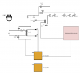
Did a quick drawing of how it is wired up. There are omissions (reservoir caps, for instance), but the grounding scheme should be correct (I think) - although I am scratching my head quite a bit. I had to find some software to draw this, so it is a bit crude. I will improve!
Now, there are, as said, pieces missing. For example, there are two 5V regulators each getting 12V. But one of them seems to get power from the other monoblock, and another delivers power to the other monoblock - so there is some kind of interconnection here. It might be that the regulator feeding the MCU gets power from the other monoblock, but they are wired the same, with same transformers, so for all intents and purposes, it should be the same (?).
Hope this helps.
Attachments
Last edited:
- Home
- Amplifiers
- Power Supplies
- Conrad Johnson preamp hiccups on line noise