Maybe either of these alone will solve my problem?
Isolation Transformer 1: 1/2: 1 Audio Balancer - Audiophonics
or
Module unbalanced to balanced symetrizer NE5532 BTL stereo - Audiophonics
Isolation Transformer 1: 1/2: 1 Audio Balancer - Audiophonics
or
Module unbalanced to balanced symetrizer NE5532 BTL stereo - Audiophonics
I know you have already put more work into this than i could ask for sgross, but you would do me a great favor if you could update the resistor values with your best guesses to take the input impedances of the 100AS2 and 200AS2 respectivly into account.
It would be great to see if this could be solved without adding more complexity and cost.
It would be great to see if this could be solved without adding more complexity and cost.
I'd rather assume it's the combination of lowest driver sensitivity and the fact that it's likely to be large enough (12" or even 15"?) for frequency response to take a nosedive past about 3 kHz.The sensitivity of the midbass driver connnected to the 200AS2-modules is close to 99db/1m at it's most sensitive. The bass drivers connected to the 700AS2 is closer to 95/1m peak sensitivity, but i didn't hear much noise from those. Hopefully a better input stage as you suggested.
Your amplifier really sort of is 3 sizes too big. Even in the bass department, I reckon the 100AS2 would have gotten the job done. Or something based on an LM3886, with an LM1876 for mids and highs (the latter with passive attenuation). You could have used a linear power supply with a modestly-sized transformer and few issues with mains leakage, in something built as IEC Class II (double-insulated)... perhaps with a safety (Y2) capacitor from secondary-side ground to PE if transformer leakage really had to be tamed. Then you wouldn't have had half the issues with the MiniDSP either (except for the gain). Oh well, it is what it is.
Yeah, kinda. You can basically use balanced connections but different impedances on both legs, but then output impedance has to be different as well. Also, performance would degrade at higher frequencies because parasitic capacitance of hot and cold are (roughly if not 100%) the same.Will the current resistor-values in your sketch be wrong then because of this input impedance mismatch?
Bad common-mode rejection and as such higher sensitivity to ground loop issues.What is the effect of bad impedance-matching?
Yes! Much improved, at least. Input impedance is a bit on the low side otherwise anyway.Could these problems be solved with an input buffer?
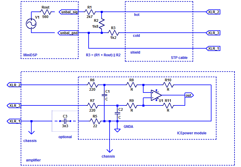
The 200AS2 datasheet shows how this is normally intended to be used, with the lower-impedance "cold" input serving as a ground sense for an unbalanced input stage. They're not saying how to interface a legit balanced input. I guess you could connect a balanced receiver just the same (always an opportunity to get the gain down, too!). Seems a bit silly to go balanced > unbalanced > balanced, but hey, it should work.
From what I've seen the integrated ADC isn't exactly great anyway.In my current use, the miniDSP are driven by preouts from a receiver. I just noticed that the analog inputs on the minidsp are very noisy indeed. I'm going to experiment with using an external ADC between the preouts and the minidsp. That way i could potentially decouple the grounds by using optical.
Here you go:I know you have already put more work into this than i could ask for sgross, but you would do me a great favor if you could update the resistor values with your best guesses to take the input impedances of the 100AS2 and 200AS2 respectivly into account.
Attachments
I chose these modules mostly to have an upgrade path in the future, in case i want to build some less sensitive speakers with a conventional tweeter.
I have soldered it up and tested it now, and it works great. The noise is reduced by more than the 10db attenuation. It's all thanks to you sgrossklass, I truly appreciate it!
Next step is to find a way to use the digital inputs on the minidsp. I'm searching for a reasonably priced RCA to toslink, but until i can find that i'll try a toslink splitter directly from the pc to the two minidsp's. Won't have surround or any way of connecting other sources, but about 10db better dynamic range because of much lower noise floor.
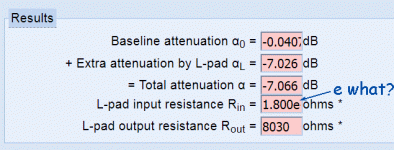
I noticed that I actually got the calculation somewhat wrong - so much for using online L-pad calculators. Those just don't allow for custom input impedance or finite source impedance. Looks like I'll have to write my own (again), this is just too tedious to do by hand every time. I'll keep you posted.
Part 1 of universal L-pad calculator is now up. Now for the fun part, calculate R1 and R2 for any two of (αL, Rin, Rout)...

This is great. And it is a useful tool for understanding the circuit. I've learned a lot!
If i understand correctly, ideally the hot and cold input should see a similar impedance to optimize noise rejection. Primarily (or only?) noise picked up by the cable. However in this case the cold side should see a slightly lower impedance because the amplifier input is actually lower impedance on the cold side.
If i understand correctly, ideally the hot and cold input should see a similar impedance to optimize noise rejection. Primarily (or only?) noise picked up by the cable. However in this case the cold side should see a slightly lower impedance because the amplifier input is actually lower impedance on the cold side.
Last edited:
Part 1 of universal L-pad calculator is now up....
Thanks.
Results are truncated to 4 figures?
<label for="liAlpha0">Baseline attenuation α<sub>0</sub> =</label>
<input size="4" readonly="readonly" name="alpha0" id="liAlpha0" value="" type="text"> dB<br>
"1.800e+4" needs 8 characters.
Attachments
These amplifiers are now being used for the speaker it was intended for, so i no longer need the attentuation. I just need to connect the miniDSP to the 100AS2 and 200AS2 without inducing unnecessary noise or distortion. The cable length between source and amplifier is around 15cm. Do i need resistors at all in this case?
I have some spare 700as2 modules that I would like to make use of. Ideally I would like each module to power one sub.
Can I use only one channel of the 700as2? Will I need to follow the instructions outlined in this thread?
Many thanks for any guidance here.
Can I use only one channel of the 700as2? Will I need to follow the instructions outlined in this thread?
Many thanks for any guidance here.
Apologies for multi-posting here but I’m trying to think this through and keep remembering things of importance;
Each sub will receive one side of a stereo signal. It would be single ended input, single ended output. Just using one channel of each module start to finish.
Each sub will receive one side of a stereo signal. It would be single ended input, single ended output. Just using one channel of each module start to finish.
- Home
- Source & Line
- Analog Line Level
- Connecting single ended to Icepower modules