I just built an amplifier with three icepower modules in them. 100AS2, 200AS2 and 700AS2. They all have balanced inputs, But all my outputs are single ended.
Currently i have connected source ground to both amplifier audio ground and the inverting signal input, and connected my source signal to the non-inverting input.
The amplifier is now very sensitive to ground noise. The noise floor increases for every component that gets its ground linked to the audio ground.
Have i conncted this single ended to balanced wrong?
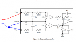
700AS2:

100 and 200AS2:

Currently i have connected source ground to both amplifier audio ground and the inverting signal input, and connected my source signal to the non-inverting input.
The amplifier is now very sensitive to ground noise. The noise floor increases for every component that gets its ground linked to the audio ground.
Have i conncted this single ended to balanced wrong?
700AS2:
100 and 200AS2:
Attachments
Last edited:
I don't know, and would greatly appreciate if someone does! I did try to simply cut the amplifier audio ground, leaving it disconnected, and that caused massive noise.
I guess i should revisit cutting the connection to GNDA then. Should GNDA be left disconnected then?
I tried again with the GNDA disconnected, and source connected only to the inverting and non-inverting inputs. That caused much more noise. I then tried adding a 100ohm resistor between source gnd and amplifier GNDA, this reduced the noise somewhat but still more then a direct connection
Already with only a Minidsp 2x4 HD connected, the noise floor is about 10db too high for the woofers, and 20db too high for the horn. The miniDSP is not grounded.
The noise floor is too high even with nothing connected at all. It's mostly white noise. very little to no low frequency hum.
The noise floor is too high even with nothing connected at all. It's mostly white noise. very little to no low frequency hum.
Last edited:
well with nothing connected isn't it just an antenna loop? the noise floor would increase,no?
ground the input of the minidsp, is the noise still there?
ground the input of the minidsp, is the noise still there?
Last edited:
If you need the GNDA connection, use the shield of a shielded twisted pair cable or a separate wire if need be, so the ground currents are carried alongside the signal connections.
How is the amplifier wired up? Did you follow the grounding scheme suggested in the datasheet? It's a bit weird tbh, and definitely not AES48 compliant:
1. Do hook up input pin 1 (shield) to chassis as directly as possible.
2. Run balanced twisted pair cabling to ICEpower module, but either do not hook up the shield at the module at all or via 1...10 nF ceramic.
For testing purposes, see whether you don't have a traditional transformer power supply that'll fit the MiniDSP's +12VDC barrel jack.
You may just have a plain gain staging problem as well. The MiniDSP's output dynamic range is something around 103 dB @ 2 Vrms, so that would be ~14 µV of output noise. The 700AS2 module has a gain of 27.4 dB, which would bring this up to ~330 µV. What's the sensitivity of your horn - I'd guess rather more than 100 dB / 2.83 V / m? Output noise level 20 dB too high sounds about right for this scenario tbh. 🙁 At 100 dB sensitivity, for 0 dB SPL @ 1 m you need a noise level of 28 µV.
I would suggest
1. making passive line-level attenuators for the MiniDSP outputs, approx. 10 dB each, with balanced cabling hooked up to them.
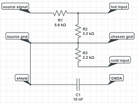
a) L-pad, maybe R1 = 5.6k / R2 = 3.3k, signal output hooked up to "hot" wire of cable
b) between "cold" wire of cable and output ground, connect (R1 + 560 ohm)||R2 to match impedance - in our example, 2.2k should be close enough
2. attenuating the horn passively by another ~10 dB, so its sensitivity is more in line with the other drivers. (In the unlikely event it performs better at near-zero output impedance, use an L-pad of suitable values instead of a plain series resistor.)
How is the amplifier wired up? Did you follow the grounding scheme suggested in the datasheet? It's a bit weird tbh, and definitely not AES48 compliant:
I have a feeling someone hadn't read Bruno Putzeys when they designed this. It's messy. Why are they even bothering to connect input cable shield to GNDA, if via a 22 ohm resistor? This is just garbage. I would suggest the following alteration:To reduce the risk of hum, it is not recommended to connect GNDA directly to Chassis at the input signal connector.
1. Do hook up input pin 1 (shield) to chassis as directly as possible.
2. Run balanced twisted pair cabling to ICEpower module, but either do not hook up the shield at the module at all or via 1...10 nF ceramic.
For testing purposes, see whether you don't have a traditional transformer power supply that'll fit the MiniDSP's +12VDC barrel jack.
You may just have a plain gain staging problem as well. The MiniDSP's output dynamic range is something around 103 dB @ 2 Vrms, so that would be ~14 µV of output noise. The 700AS2 module has a gain of 27.4 dB, which would bring this up to ~330 µV. What's the sensitivity of your horn - I'd guess rather more than 100 dB / 2.83 V / m? Output noise level 20 dB too high sounds about right for this scenario tbh. 🙁 At 100 dB sensitivity, for 0 dB SPL @ 1 m you need a noise level of 28 µV.
I would suggest
1. making passive line-level attenuators for the MiniDSP outputs, approx. 10 dB each, with balanced cabling hooked up to them.
a) L-pad, maybe R1 = 5.6k / R2 = 3.3k, signal output hooked up to "hot" wire of cable
b) between "cold" wire of cable and output ground, connect (R1 + 560 ohm)||R2 to match impedance - in our example, 2.2k should be close enough
2. attenuating the horn passively by another ~10 dB, so its sensitivity is more in line with the other drivers. (In the unlikely event it performs better at near-zero output impedance, use an L-pad of suitable values instead of a plain series resistor.)

Nope, unbalanced with RCAs (560 ohm output R). Impedance balancing an unbalanced output is fairly straightforward though, and in this case I would combine it with an output attenuator if one turns out to be required anyway.does that model Minidsp have balanced out??
(BTW, I suggested some passive attenuation earlier because the noise floor of the power amp itself may very well be pushing it for the horn. Also, one may have to drop attenuator resistor values a bit, an effective source impedance of 4.4 kOhms does seem a tad high in retrospect.)
Last edited:
Thank you very much. I will try. The sensitivity of the horn is over 110db/1m.
I've never been so close to rage-quiting this hobby. I thought these Icepower modules was supposed to be a high end solution that would plug and play to solve the noise issues i had when using old recievers as power amps. If anything it's worse, as it is much more sensitive to ground noise. The pc now feeding low crackling noises into the horn. Grounding everything together with high gauge wire helps slightly, but still worse than a 15year old H/K receiver.
I've never been so close to rage-quiting this hobby. I thought these Icepower modules was supposed to be a high end solution that would plug and play to solve the noise issues i had when using old recievers as power amps. If anything it's worse, as it is much more sensitive to ground noise. The pc now feeding low crackling noises into the horn. Grounding everything together with high gauge wire helps slightly, but still worse than a 15year old H/K receiver.
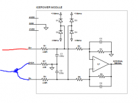
Is this what you meant sgrossklass? It's really fiddly to make changes to the amplifier, so i want to make sure its right before i start. I can't tell you how much i appreciate your help. A real saviour. According to the documentation, the input impedance of the amplifier is around 7kohm.

Attachments
Last edited:
Uh-oh. That's not just high, it's bordering on stratospheric. You would probably have much better luck trying to drive that with a stout headphone amplifier, traditional speaker power amps have way too much gain and output noise. (A Benchmark AHB2 would also do, as it manages a 113 dB SINAD at 5W/4ohm levels in low gain mode according to ASR, but that's very lonely at the top and other well-respected power amps make it to 105 dB at best, which is still solid.) Some people have used the trusty Amp Camp Amp (ACA) to drive horns like yours for this very reason - low gain, low output noise, and distortion that is unlikely to exceed the driver's despite being objectively abysmal (at 1 W level, we're talking -50 dB H2 and -70 dB H3, and that's good for >110 dB @ 1 m in your case).Thank you very much. I will try. The sensitivity of the horn is over 110db/1m.
Or alternatively, plenty of passive attenuation as I suggested. Possibly up to 20 dB - then a 50 wpc amplifier would still be good for 107 dB @ 1 m while your 72 ohm series resistor is dissipating 4.5 W. The ICEpower modules want a 4-8 ohm load for best gain flatness though, don't they?
What sort of peak levels are you going to need? It is obvious at this point that you won't be able to have both completely inaudible output noise and rock concert levels at once, the MiniDSP alone couldn't do that.
Which is saying something, given that H/K receivers 15 years ago (at least their surround ones) were generally shipping with 5V-only PGAs and had a measly 95 dB SNR spec.I've never been so close to rage-quiting this hobby. I thought these Icepower modules was supposed to be a high end solution that would plug and play to solve the noise issues i had when using old recievers as power amps. If anything it's worse, as it is much more sensitive to ground noise. The pc now feeding low crackling noises into the horn. Grounding everything together with high gauge wire helps slightly, but still worse than a 15year old H/K receiver.
Now that was with a passive crossover though, wasn't it? You were just missing some of the design challenges that come with trying to go active. Plug'n'play, well, you wish.
Not quite.Is this what you meant sgrossklass?
Attachments
You are my hero. Thank you!
I've been doing active xo only for about the past 10 years, i'm too lazy to develop passive xo's anymore. Using the HK amp i also used about 8db passive attenuation, which brought the noise down some, but not enough.
I'm targeting 105db peak spl at 1m.
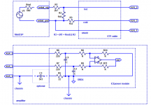
Currently twisted pair shielded signal cables are routed directly from the minidsp, through a hole in the chassis, and then terminated directly on the module. The intention was to have the shielding go unbroken for the entire length.
Would it be ok to have the L-pad placed on the amplifier-side of the cable? Does all the resistor-values have to be changed if i want to increase the attenuation?
I can experiment with the passive attenuation. See how the amplifier reacts to a high impedance load.
But seriously, thank you for taking the time to help me out.
I've been doing active xo only for about the past 10 years, i'm too lazy to develop passive xo's anymore. Using the HK amp i also used about 8db passive attenuation, which brought the noise down some, but not enough.
I'm targeting 105db peak spl at 1m.
Currently twisted pair shielded signal cables are routed directly from the minidsp, through a hole in the chassis, and then terminated directly on the module. The intention was to have the shielding go unbroken for the entire length.
Would it be ok to have the L-pad placed on the amplifier-side of the cable? Does all the resistor-values have to be changed if i want to increase the attenuation?
I can experiment with the passive attenuation. See how the amplifier reacts to a high impedance load.
But seriously, thank you for taking the time to help me out.
Not that much (the horn will be terribly bored I'm sure 😉 ), so that should be doable. How sensitive are the other drivers?I'm targeting 105db peak spl at 1m.
Looks like total gain required from MiniDSP output to horn input would be about -3 dB. Yes, that's less than unity. So you could use up to 27-30 dB of attenuation.
Wait, the 100AS2 module only has 21 dB of voltage gain. So 21-24 dB of attenuation then. Your ears clearly weren't wrong.
BTW, did you know that 110 dB / 2.83 V / m translates into 101 dB / 1 V / m? A Sennheiser HD650 is rated 103 dB / 1 V. So voltage wise, you're literally in headphone territory @ 1 m.
Basically yes, but you would have to change the cable for unbalanced coax (shielded audio cable), with an extra shield connection in parallel that remains connected as-is. Double-shielded coax would be ideal but an extra wire should get the job done as well.Currently twisted pair shielded signal cables are routed directly from the minidsp, through a hole in the chassis, and then terminated directly on the module. The intention was to have the shielding go unbroken for the entire length.
Would it be ok to have the L-pad placed on the amplifier-side of the cable?
Alternatively, you could first balance the cabling with 560 ohms in series with "cold", then run STP to the amp, and use a balanced attenuator there - basically a double L-pad, connected between (hot and shield) and (cold and shield), respectively. Since there are twice as many resistors, resistor values have to be halved. Attenuation would change slightly as well, as effective MiniDSP output impedance as seen at the cable end is now (560 + 560) ohms.
I suggest you make a new chassis ground hookup point near the amplifier module's input connector for the cable shields. You can run a capacitor from input GNDA to the same chasssis ground as suggested earlier but it's not strictly needed.
Yes.Does all the resistor-values have to be changed if i want to increase the attenuation?
Basically it's always a balancing act between avoiding excessive source output loading (not sure about the capabilities of the MiniDSP output but I'd rather avoid <5 kOhms) and having effective source impedance as seen by the amplifier become too large. Higher division ratios give better results in this respect.
If in doubt, you can always go for an L-pad with some higher-wattage resistors. With an 8 ohm driver, 4.7 ohms + 3.3 ohms would give around -10 dB... I doubt you'd really need more than 5 W parts for the horn.I can experiment with the passive attenuation. See how the amplifier reacts to a high impedance load.
This should also give you an idea how much passive attenuation you need to suppress inherent amplifier noise sufficiently. Once you have that figured out, you'll know how much you still need between the MiniDSP and amplifier. Then we can recalculate the resistor values accordingly.
BTW, I hope you're going for one of the MiniDSP's digital inputs.
Last edited:
PS - I just noticed the input impedance spec on the 100AS2 module while studying its datasheet:
2.8 kOhms for IN+, 1.8 kOhms for IN-. Seriously? ICEpower, why?
Less noise, I'm guessing, but why are they recommending an output with 100 ohms on both sides then instead of 62 ohms on the ground/cold side? Because they are using the same illustration everywhere?
200AS2 datasheet revealed
3 kOhms for IN+, 1.8 kOhms for IN-
Slightly different again.
The 700AS2 is rated at 36k IN+ and IN-. Whether that means either or across both I'm not sure, it's high enough anyway. Ah yes, it's got an input buffer on-board, that's why. The smaller modules could use one of those, too.
This is going to complicate our attenuation and impedance matching business a bit. Some empirical CMRR testing may have to be done to verify the specs.
The sensitivity of the midbass driver connnected to the 200AS2-modules is close to 99db/1m at it's most sensitive. The bass drivers connected to the 700AS2 is closer to 95/1m peak sensitivity, but i didn't hear much noise from those. Hopefully a better input stage as you suggested.
Will the current resistor-values in your sketch be wrong then because of this input impedance mismatch? What is the effect of bad impedance-matching? Could these problems be solved with an input buffer?
I don't mean to be lazy with all these questions, i'm trying to understand as best as i can, but it is difficult without the experience. Your help means very much to me.
In my current use, the miniDSP are driven by preouts from a receiver. I just noticed that the analog inputs on the minidsp are very noisy indeed. I'm going to experiment with using an external ADC between the preouts and the minidsp. That way i could potentially decouple the grounds by using optical.
Last edited:
- Home
- Source & Line
- Analog Line Level
- Connecting single ended to Icepower modules