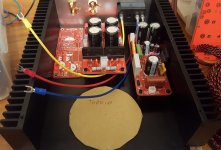
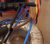
I'm trying to figure out what the best way is to connect the input wires for the toroid transformer to the output wires from the mains input switch/fuse/IEC kettle connector unit.
Do I:
I'm unsure how much space I have in the case, want to try to make it look neat.
Anyone have any recommendations or tips please? Thank you
Do I:
- solder the wires together and cover only in a couple layers of heat shrink wrapping? (doesnt seem a good idea given 240V mains)
- use a crimp female to female thing (might be called a "butt splice terminal" but unsure of the name, An externally hosted image should be here but it was not working when we last tested it.) with a bit of heatshrink?
- Use a connector strip terminal block (the 80s/90s style with screw terminals)? Not sure how to mount them - usually I've seen them with self tapping wood screws
- Use a terminal block for semi circle connectors like: Dual Row Fixed Screw Terminal Block 15A 600V Electric Barrier Connector | eBay
- use something else?
I'm unsure how much space I have in the case, want to try to make it look neat.
Anyone have any recommendations or tips please? Thank you
Attachments
@PRR Thanks for your suggestion. I just took a look at Wago 221 series and 222 series, looks nice. Presumably I'd have to mount it somehow in the case (222 series seems to have a mounting system but need to check the sizes whether it will fit in my case) so that it's not flapping about in the breeze.
I would solder them to the IEC & ON OFF switch and put heat-shrink over the connection.
Solder and heat-shrink works fine for 240V. One layer is enough. I usually put a large Tesa Perfect cloth based tape covering the IEC and switch. There are also some rubber boots.
I've also seen many gear with these types. Mostly in speaker plate amps.
Closed end connectors 22-16AWG nylon wire terminal kit
@MAAC0
I may have to try the solder + heatshink. It just makes it annoying as i'd have a wire from one end to the other and if I need to remove or replace I have to unsolder. I prefer something with a connector so it can be disconnected.
That's why I went with the Molex Mini-fit Jr connectors for the PSU and amplifier boards - can just disconnect and connect for replacement / servicing / assembly.
I've not yet checked the dimensions, but something like this might be ok? CTRICALVER 10 pcs SPL-2 Compact Wire Connectors, Conductor Wire Clamp Terminal Block with Levers for Solid, Stranded, and Flexible Wire Cables, Wire Connectors with fixing screws: Amazon.co.uk: Business, Industry & Science
Picture says 250V but the description says 600V so I'd have thought it'd be safe - the mounting for it can be done onto the bottom panel.
These should work for you. The come in two different "gauges" and different number of positions. I just buy the 12 position ones and snip off the number I want. I find the smaller ones to work for everything I need. The accept from 22 - 14g wire. If I want to be fancy, I terminate with the proper sized ferrule.
https://www.mouser.com/ProductDetail/Altech/HE10HWPR-12?qs=DeBbiv%2F5BpBsoOGKa%2FQhjw%3D%3D
https://www.amazon.com/Ferrules-Sopoby-Insulated-Terminal-Electrical/dp/B06XCX8FMZ
https://www.mouser.com/ProductDetail/Altech/HE10HWPR-12?qs=DeBbiv%2F5BpBsoOGKa%2FQhjw%3D%3D
https://www.amazon.com/Ferrules-Sopoby-Insulated-Terminal-Electrical/dp/B06XCX8FMZ
Last edited:
If the wires from the toroid will reach you could crimp female spades and mount direct to the IEC: They come in fully insulated type.
If they won't reach I'd just join the wires by solder and heatshrink after cutting the surplus fork connector off. You already have a push-on connector, why add another?
If they won't reach I'd just join the wires by solder and heatshrink after cutting the surplus fork connector off. You already have a push-on connector, why add another?
Frankly, if you have to ask, maybe you should not be working on mains wires. Smoke, fire, shock.
We treat this part as-if it was wiring in the wall, because it really is the same juice.
Wagos can just flop around in a box. Or is your amplifier doing acrobatics?
Solder is legacy technology. At mains power level, a downstream short will MELT solder and FLING it around.
Crimps MUST have the right crimper and an experienced operator. I'm tired of pulling "crimps" apart with gentle handing.
Wire nuts are secure and safe only if you have experience. They are rarely used in the UK because early (pre-1960) wirenuts gave big trouble. They are widely used in the US, and a journeyman Electrician can joint wires quickly and safely, but homeowner wire-nuts are dubious and usually bad.
Wagos can be done wrong but it is not as easy as the other techniques. Use the right size (gauge-range), which may be one or two sizes down from wall wiring. (I forget how wide a range Wagos take because they are rare in the US.)
Yes, "euro-blocks" are good devices but they sure look better if screwed down, and I never have screws that small.
EDIT-- I mean Wago lever-blocks. I just noted that Wago makes a push-in (no lever), which I would not trust on stranded transformer leads.
Last edited:
Well if you have never used screws that small then maybe you shouldn't be using screws! Come on. This is a DIY forum and our "job" is to help people do stuff. Of course he should be working on mains wiring within his amplifier. He knows enough to ask questions about safety. Don't be so high and mighty.
At mains power level, a downstream short will MELT solder and FLING it around.
No solder on mains side wiring?
I'm concerned.
I'm sure I have commercially built equipment with eg wires from the mains inlet soldered to the inlet fuse pcb. ATX supplies with wires from the IEC inlet soldered to the PCB. PCB fuse holders soldered...
Have I misunderstood what your meaning?
Use solder and heatshrink, it´s designed for that..
Double it for peace of mind but not really necessary.
Double it for peace of mind but not really necessary.
I started using the Wago lever locking connectors for prototyping. I was so happy with them that I use them in my finished electronics. I have never had one fail in 10 years of use.
For that to happen you need 100 or more Amperes flowing through fuse / fuse clip / switch / mains cable - plug - socket / wall wiring and everything else in that path (Kirchhoff´s Law) and most if not all those elements will melt and catch fire before soldered junction does.Solder is legacy technology. At mains power level, a downstream short will MELT solder and FLING it around.
That´s what fuses were invented for.
As a side note: I have seen plenty arced switches and fuse holders/connectors, molten wall plugs and sockets, bubbling/molten cable insulation, molten open wiring (with copper bubbles at each end) , etc.
Never ever saw molten solder flung around.
Last edited:
"...there are good and bad ways of performing the soldering."
A factory job is, we hope, good. If you hang on DIY chatrooms enough you will see really bad soldering. There is a skill that not everybody gets. Wirenuts are a real skill, made worse because sometimes it looks easy.
I much prefer a low-skill reliable joint. The lever-Wagos are pretty user-friendly. Guarded-screw euro-blocks are IMHO almost as friendly.
Yup, that is what I used for my speaker wires to splice to the jacks.Wagos.
If we are to look at the problem thoroughly, the initial question is by no means obvious. The old IEC 60065 standard spends pages on the subject, and for the new 62368-1 there is at least as much work to do to be sure of safe work. Welded connections are allowed, but with limitations. The cables must be secured to the frame. To do a truly flawless job, you need an IEC connector from which the conductors come out directly (therefore with an integrated filter or protected by a rubber shoe); its cables and those of the transformer enter a small plastic box closed by a lid, fixed to the frame, inside which a screw terminal block or even the wago block is placed. Cables entering this box must be secured inside. This ensures that even when the lid of the device is opened, there is no exposed mains voltage. The plastic box must be able to whistand a maximum temperature of at least 150C without deformation.
The folowing text is from IEC 60065 standard (Audio, video and similar electronic apparatus – Safety requirements):
For apparatus with non-detachable MAINS supply cords, the connection of the individual conductors to the internal wiring of the apparatus shall be accomplished by any means that will provide a reliable electrical and mechanical connection, except that the supply conductors and the protective earthing conductor of a non-detachable MAINS cord or cable shall not be soldered directly to the conductors of a PRINTED BOARD. Soldered, crimped and similar connections may be used for the connection of external conductors. For soldered or crimped connections, barriers shall be provided so that CLEARANCES and CREEPAGE DISTANCES cannot be reduced to less than the values specified in clause 13 should the conductor break away at a soldered joint or slip out of a crimped connection. Alternatively, the conductors shall be positioned or fixed in such a way that reliance is not placed upon the connection alone to maintain the conductors in position.
Thanks all.
I went for a Wago-style connector block in a 2-in, 2-out configuration.
I've got some TPE netting tube which I will cover the mains cabling in, and use shrink wrap tube where I can (e.g. places where spade terminals or soldered connections to switches).
I went for a Wago-style connector block in a 2-in, 2-out configuration.
I've got some TPE netting tube which I will cover the mains cabling in, and use shrink wrap tube where I can (e.g. places where spade terminals or soldered connections to switches).
If we are to look at the problem thoroughly, the initial question is by no means obvious. The old IEC 60065 standard spends pages on the subject, and for the new 62368-1 there is at least as much work to do to be sure of safe work. Welded connections are allowed, but with limitations. The cables must be secured to the frame. To do a truly flawless job, you need an IEC connector from which the conductors come out directly (therefore with an integrated filter or protected by a rubber shoe); its cables and those of the transformer enter a small plastic box closed by a lid, fixed to the frame, inside which a screw terminal block or even the wago block is placed. Cables entering this box must be secured inside. This ensures that even when the lid of the device is opened, there is no exposed mains voltage. The plastic box must be able to whistand a maximum temperature of at least 150C without deformation.
The folowing text is from IEC 60065 standard (Audio, video and similar electronic apparatus – Safety requirements):
For apparatus with non-detachable MAINS supply cords, the connection of the individual conductors to the internal wiring of the apparatus shall be accomplished by any means that will provide a reliable electrical and mechanical connection, except that the supply conductors and the protective earthing conductor of a non-detachable MAINS cord or cable shall not be soldered directly to the conductors of a PRINTED BOARD. Soldered, crimped and similar connections may be used for the connection of external conductors. For soldered or crimped connections, barriers shall be provided so that CLEARANCES and CREEPAGE DISTANCES cannot be reduced to less than the values specified in clause 13 should the conductor break away at a soldered joint or slip out of a crimped connection. Alternatively, the conductors shall be positioned or fixed in such a way that reliance is not placed upon the connection alone to maintain the conductors in position.
I wonder if anyone goes back and retrofits their builds when more stringent standards are enacted?

- Home
- Design & Build
- Construction Tips
- Connecting mains switch connector to toroid?