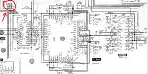
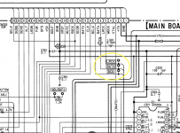
Hey guys! There is a board from Sony CDP-515. I want to connect it via the I2s bus to the media player and use it as an external DAC. Who can tell you where to hook the MCLK wire? Maybe someone has already experimented?
Attachments
Last edited:
Я думаю, что вы можете получить некоторые ответы, если вы разместили на английском языке.
Кажется, это язык выбора на этом форуме.
Кажется, это язык выбора на этом форуме.
I'm confused, but where exactly should I connect them?Это строки данных. Не забудьте подключить часы для синхронизации.

Because post #1 was originally in Russian and then edited. Everything followed on from that event.
I replied in Russian because I can. Should have been in English but I was always different with my own mind.
kumiroff, если вам нужно задать такой вопрос, вы знаете, что делаете?
kumiroff, если вам нужно задать такой вопрос, вы знаете, что делаете?
Beware, the SONY IC will not output i2S.
I can't remember which format it is, left justified, right justified or what.
But it's not i2S.
I can't remember which format it is, left justified, right justified or what.
But it's not i2S.
CXD2515Q.
Pin 62 MCLK 384Fs
Pin 47 BCLK 48Fs
Pin 46 DATA LSB/Right justified.
Pin 45 LRCK Fs
Pin 44 WDCK 2Fs
Pin 62 MCLK 384Fs
Pin 47 BCLK 48Fs
Pin 46 DATA LSB/Right justified.
Pin 45 LRCK Fs
Pin 44 WDCK 2Fs
It turns out that without 2515, 2567+2562 will not work? I repeat once again: I want to connect a board with 2567+2562 to the I2C bus of the media player and use this board as a DAC.CXD2515Q.
Pin 62 MCLK 384Fs
Pin 47 BCLK 48Fs
Pin 46 DATA LSB/Right justified.
Pin 45 LRCK Fs
Pin 44 WDCK 2Fs
Sony chips use most times Sony format (16b in 24b frame , LSB/Right justified ) , so you cannot use I2S connection. (need some hardware, to convert format).I repeat once again: I want to connect a board with 2567+2562 to the I2C bus
And what can you recommend?нужно некоторое оборудование, чтобы преобразовать формат
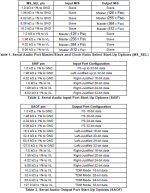
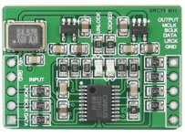
If nothing else helps, you could use a ASRC board with CS8422. Very convenient and cheap little boards where you could set-up all 3-wire input and output formats with only one (two) resistors as you need.
Even without studying all the datasheet, it takes you only the correct input/output wiring, a handfull of 1k 0805 resistors (even better if you have 2k and 4k also by hand - you just combine them as needed) according to the table attached.
Well, maybe you should read the CS8421 datasheet too 😉
Edit: output sample rate (=MCLK) depends on the crystal oscillator used. Get an 11,286MHz XO for 44,1kHz to fit almost everthing. Some boards had 24,576Mhz installed while others I received with 27MHz (~217kHz).
Attachments
sorry, but from the level of your question (not knowing about the formats ...) : forget it.And what can you recommend?
otherwise: read the data sheets, fix , what you want to do , what is your target ? and then : ask for something - what is your idea , your target ??
something i wrote for my CDP-X303ES USB DAC conversion in 2019, that configures the cxd2567m+cxd2562q:
I2SoverUSB v.III also connects in place of old 45Mhz XTAL.
i still use this modded CDP to this day
C:
#include <avr/interrupt.h>
#include <avr/io.h>
#include <avr/power.h>
#include <avr/sleep.h>
#include <stdint.h>
#include <util/delay.h>

#define AMUTE PB0
#define USB_POWER PB1
#define ATT PD5
#define SHIFT PD4
#define LATCH PD3

static void send(uint16_t word)
{
    //    if (PORTA & _BV(PA0))
    //        return;

    // Send 16 bits starting with LSB, just like the CDP
    for (uint8_t bit = 0; bit < 16; bit++) {
        PORTD &= ~_BV(SHIFT);

        if ((word >> bit) & 1) {
            PORTD |= _BV(ATT);
        } else {
            PORTD &= ~_BV(ATT);
        }

        // the part allows lower wait times of <600ns, but doing roughly what the CDP does in this whole function
        _delay_us(5);
        PORTD |= _BV(SHIFT);
        _delay_us(5);
    }

    PORTD &= ~_BV(LATCH);
    _delay_us(5);
    PORTD |= _BV(LATCH);
    _delay_us(32);
}

int main(void)
{
    PORTA = _BV(PA0) | _BV(PA1);

    PORTB = _BV(AMUTE);
    DDRB = _BV(AMUTE) | _BV(USB_POWER);

    PORTD = _BV(ATT) | _BV(SHIFT) | _BV(LATCH); // puls them up before changing direction, so that they don't go down even for the short time until DDRD is set
    DDRD = _BV(ATT) | _BV(SHIFT) | _BV(LATCH);

    // switching on I2SoverUSB's USB section before DAC init, therwise DAC fails to init properly
    PORTB |= _BV(USB_POWER); // switch on the optocoupler LED. Could probably just connect it to CDP's RST but whatever. No reason to use an optocoupler, a transistor would do but whatever.
    _delay_ms(3000); // DAC fails to init without delay

    switch (PINA & (_BV(PA0) | _BV(PA1))) { // DIP switches on my PCB
        // exactly as the CDP does, except here attenuations immediately follow the 3 init commands, whereas on the CDP full attenuation happens ~4 seconds later, followed by the 0db half a second later
        case 0b00:
            send(0b0100010000010000);
            send(0b1000000001000000);
            send(0b0001000000000000); // on the CDP it's 0x1000, 0x2000 makes no audible difference
            send(0b0000000000000000); // set full attenuation
            send(0b0000010000000000); // set attenuation to 0 dB (1024 steps accross [1;0x400], zero being complete attenuation)
            break;
        case 0b01: // same just without the redundant(?) full attenuation
            send(0b0100010000010000);
            send(0b1000000001000000);
            send(0b0001000000000000); // can't hear it. might as well skip it altogether
            send(0b0000010000000000); // set attenuation to 0 dB (1024 steps accross [1;0x400], zero being complete attenuation)
            break;
        case 0b10: // without the redundant attenuation and 32bit frame?
            send(0b0100010000100000); // makes the 32bit channel frame work i dunno
            send(0b1000000001000000);
            send(0b0001000000000000); // can't hear it. might as well skip it altogether
            send(0b0000010000000000); // set attenuation to 0 dB (1024 steps accross [1;0x400], zero being complete attenuation)
            break;
        default:
            for (;;) { // signal fault state forever
                PORTB ^= _BV(AMUTE);
                _delay_ms(1000);
            }
    }

    PORTB &= ~_BV(AMUTE); // OK to unmute now

    // Power down the AVR
    cli();
    power_all_disable();
    set_sleep_mode(SLEEP_MODE_PWR_DOWN);
    sleep_enable();
    sleep_cpu();

    for (;;) { // it should never reach here
        PORTB ^= _BV(AMUTE);
        _delay_ms(0xff);
    }
}i still use this modded CDP to this day
- Home
- Source & Line
- Digital Source
- Connecting CXD2567M+CXD2562Q via I2S