I need another V+ from the new bridged rectifier to power another circuit.
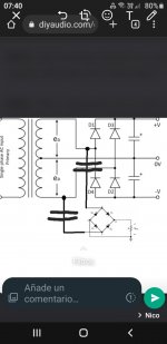
it might best explained with a diagram.
- I currently have the V+/V- supply in the diagram.
- I need to tap into the transformer to power up another circuit (lower portion of the diagram with the bridge rectifier)
- The transformer that I'm using have 2 secondaries connected in series. The connected wires become my center-tap ground.
Is this possible? If yes, what changes do I need (if required) to make it work?
Thanks a lot.
PS. apologies for the quality of the diagram. It's a mashed up I made using MS Paint. 😀
-------------
Edit1: I thought just came to mind. Instead of tapping into the transformer, perhaps I can tap V+ from the first capacitor immediately after the existing rectifiers?
Edit2: the existing supply is a regulated +/- 12V. The new supply will give me more than +12V.
Edit3: The 2 grounds from both supplies are not connected.
Last edited:
I am not completely sure what you want to achieve when you say "I need another V+ from the new bridged rectifier to power another circuit".
But to try help you describing your requirement, then please explain, why you do not just use the existing V+ as described in your edit?
That would give you a V+ (referred to ground).
BTW: Is it intended that the added bridge rectifier does not include a smoothing capacitor? - because as the circuit is drawn now, you will just get a rectified AC with a peak value that is the same as the voltage difference between V+ and V- (that is: 2 * V+).
Cheers, Martin

It looks like the sensible solution: as the previous poster remarked, your proposed scheme will result in fireworks.Edit: I thought just came to mind. Instead of tapping into the transformer, perhaps I can tap V+ from the first capacitor immediately after the existing rectifiers?
If you really a "separate" supply (why?), simply duplicate D1, D3 and a suitable filter cap
@mrjayviper
Let’s talk real numbers…. What is the voltage of the existing +/- supply?
What is the voltage required of the new supply? It is a single, I.E., 0-12v instead of +/-12v?
Let’s talk real numbers…. What is the voltage of the existing +/- supply?
What is the voltage required of the new supply? It is a single, I.E., 0-12v instead of +/-12v?
existing supply is around +/- 12V. requirement for new supply is more than 12V.@mrjayviper
Let’s talk real numbers…. What is the voltage of the existing +/- supply?
What is the voltage required of the new supply? It is a single, I.E., 0-12v instead of +/-12v?
I forgot to mention the ground for the 2 supplies is not connected. Does that changes anything?
Thanks again
It looks like the sensible solution: as the previous poster remarked, your proposed scheme will result in fireworks.
If you really a "separate" supply (why?), simply duplicate D1, D3 and a suitable filter cap
You cannot connect the 2nd bridge like that....boom....
I forgot to mention the ground for the 2 supplies are not connected. Does that changes anything? Thanks again
I edited my original post. Hope that makes it clearer. Thank you.I am not completely sure what you want to achieve when you say "I need another V+ from the new bridged rectifier to power another circuit".
---snip---
Cheers, Martin
So you want to make two separate supplies on one set of transformer outs? If so then no you can’t.
You say the two grounds are not connected?
If the power is off, and you connect an ohm meter between the two "grounds"
then what do you measure?
What kind of circuits do the supplies power?
If the power is off, and you connect an ohm meter between the two "grounds"
then what do you measure?
What kind of circuits do the supplies power?
Last edited:
even if their ground is not connected?So you want to make two separate supplies on one set of transformer outs? If so then no you can’t.
Yup -- no way to do it without sharing the Ground. You have a center-tap-Grounded transformer -- no number of additional rectifiers are going to provide the Ground isolation you seem to be seeking. Sorry . .
Cheers
Cheers
Last edited:
If the grounds are floating wrt.each other, AND there is no galvanic connection of any kind between the loads (no shields, no common, et.),you can create two independent supplies.even if their ground is not connected?
WHAT is the second load?
WHAT voltage does it need?
Not strictly necessary but to help clarify things, WHAT is the DC voltage between +V to 0V and -V to 0v?
Now that we are at it, WHAT us the original voltage load or what is it feeding?
Please answer all the "what" questions?, otherwise answers will easily contradict because of lack of definitions.
PS:you say "grounds are not connected", I am not so sure about that.
Also not too sure you understand "galvanic isolation".
If no graphic software available, just draw with ink on a piece of paper and upload a phone picture.
If your new load is relatively light, you can isolate AC path via two large bipolar capacitors in each AC arm of the new rectifier added. Then, reference it where you need in order to obtain the new proper voltage. Those parallel lines means the new cap to be added.
Attachments
Last edited:
- Home
- Amplifiers
- Power Supplies
- Connecting another bridge rectifier to an existing V+/V- supply