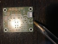
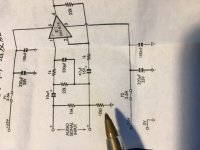
There is a discrepancy in circuit diagram and PCB markings. If you look at the attached pics 10uf capacitor is wired - “minus” towards input source on the diagram but on PCB it is other way round. Which one is correct? I thought it should be like on PCB, + towards source?
Another question is there is 10 Ohm resistor from audio ground to actual ground, but all my preamps have actual ground as audio ground. This resistor will be redundant if I connect preamp. Why is it there and what happens if it is shorted?
Another question is there is 10 Ohm resistor from audio ground to actual ground, but all my preamps have actual ground as audio ground. This resistor will be redundant if I connect preamp. Why is it there and what happens if it is shorted?
Attachments

Hi KillzoneKid
Allthough it is not really a good practice, then electrolytic capacitors can live with a reverse polarization. I recall this applies for voltages significantly less than 1 V. (but don't use tantaliums for this, they will not be happy).
The LM1875 specifies a +/- bias current (a result of bias cancellation circuitry).
This implies that the voltage across the input resistor may be of both polarities - but very small:+/- 44mV max.
So the answer is: it does not matter.
If you want to ensure the correct polarity, you will have to measure the DC at pin 1 and then mount the input capacitor accordingly.
The 10 ohm is to avoid ground loops.
There has been quite a few other threads discussing this, please try to look at these.
Cheers,
Martin
Thanks, I've ordered non polarised capacitor since making this thread, so I guess this will do. As for 10 Ohm resistor, I didnt know what exact term to search for, but now as you mentioned it, I will try again.
Sorry, the search term "LM1875 ground loop" did not return very precise results, but have a look at Star ground?
But this is DIY - and some of the fun comes from experimenting and trying things out🙂 - depending on layout and wiring it may work as you want with no further complications.
Cheers,
Martin
But this is DIY - and some of the fun comes from experimenting and trying things out🙂 - depending on layout and wiring it may work as you want with no further complications.
Cheers,
Martin
There's a thread on this kit and there is some suggestions on components such as the input cap as well as layouts.
eBay mono LM1875 kit
The 10R ground lift resistor can be changed out for a link if desired but best left as is (I 've tried it both ways). Sort of separates the signal ground from the power ground.
eBay mono LM1875 kit
The 10R ground lift resistor can be changed out for a link if desired but best left as is (I 've tried it both ways). Sort of separates the signal ground from the power ground.
Thanks for suggestion, so my preamp signal ground is the power ground, shall I connect it to the actual ground on power amp or to signal ground?
Muchos gracias. I will have all in one design so no RCAs. Huge project, Arduino based, FM radio, Bluetooth, IR control... But audio first and foremost!
The input cap only 'sees' the input offset voltage, which is typically a few mV. It's safe to ignore the polarity in that case.
If I recall correctly, the input bias current flows into the LM1875, so you'll find a negative voltage on the (+) terminal of the capacitor in the schematic. That makes the PCB orientation correct. But still. We're talking mV.
Tom
If I recall correctly, the input bias current flows into the LM1875, so you'll find a negative voltage on the (+) terminal of the capacitor in the schematic. That makes the PCB orientation correct. But still. We're talking mV.
Tom
It is true that the polarity of the bias voltage is of no consequence - as I wrote previously in my first mail.
But the LM1875 specifies a +/- bias current (a result of the bias cancellation circuitry included, at least in the datasheet provided by National) - so you can not predict the polarity of the input bias.
Cheers,
Martin
But the LM1875 specifies a +/- bias current (a result of the bias cancellation circuitry included, at least in the datasheet provided by National) - so you can not predict the polarity of the input bias.
Cheers,
Martin
Ah. I should have checked the schematic for the LM1875. I assumed its input stage was similar to that of the LM3886 (where you can predict the offset polarity).
All good.
Tom
All good.
Tom
- Home
- Amplifiers
- Chip Amps
- Confused about LM1875 kit