Just add the Vinoise trace to your plot. This will refer noise to the input and scaled for the gain.I suggest incorporating the gain into the analysis; namely, divide output noise by the gain (function of frequency) so that the you have noise density referred to the input (RTI). This aids assessment of design changes and comparison of active devices. Transistor data sheets will often show noise density vs. frequency, so RTI analysis lets you assess performance vs. manufacture's specs.
Yes - I have a small stock and would part with a few for a nominal fee and postage. SOT23 from Mouser.They have been out of production for a couple of years, since 2018 or so.
I don't know how suited it is to your application given the 1 G resistor and gate leakage currents. Probably a question for Marcel.
For the model, do a search on this site or google it. In general, noise modelling seems to be fairly accurate in LTspice, but as Mark has pointed out, many parameters are not that accurate and especially with JFETs
Last edited:
See figure 9 of https://www.nxp.com/docs/en/data-sheet/BF862.pdf for the typical gate leakage. As long as you keep the drain-gate voltage below 3 V to 4 V, it is typically just a few picoamperes at 25 degrees Celsius.
This should be good enough; as long as it is below about 52 pA, the shot noise of the gate leakage current should be less than the thermal noise current of the 1 Gohm resistor.
Mind you, there is no guarantee that the leakage of each and every BF862 is that low, so you could have a bad one. Production testing leakage currents in the picoampere range would have made the FET more expensive and it didn't matter anyway for the AM car radio front-ends it was meant for.
Last edited:
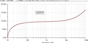
I haven't managed to get the BF862 version working yet, seems to be a problem with the BF862 model I'm currently trying to use, the input noise floor curve turns out to be virtually zero, but the cursor says 13nV. Somethings wrong somewhere.
But the JFE150 is so far the lowest noise floor at about 60% noise level of the 2N3819 version ..


But the JFE150 is so far the lowest noise floor at about 60% noise level of the 2N3819 version ..
Attachments
Last edited:
H
HAYK
I have a working model of bf862 from TI for Tina.
It is in SUBCKT form. In LTSPICE, open the file and highlight BF862 after the SUBCKT and right click to get a menu to choose create symbols.
Change the 1,2,3 into D,G,S and save, it will appear in LTSPICE auto-generated components list.
It is in SUBCKT form. In LTSPICE, open the file and highlight BF862 after the SUBCKT and right click to get a menu to choose create symbols.
Change the 1,2,3 into D,G,S and save, it will appear in LTSPICE auto-generated components list.
Attachments

H
HAYK

Won't you couple output pnp directly to preceeding JFET? Saves superfluous bias network and coupling cap.
I already have the boost converter (get 5 of them for about £5) ..
https://www.ebay.co.uk/itm/203759296836
As well as the 60v (or more) for the mic condenser It also has to provide 25V for the pre-amp. The 60V is virtually no current at all, the 25V line needs to supply about 10mA at the very most.
Applying a higher voltage to the mic capsule direct increases it's audio output level with no noise increase.
I've turned the buffer into a gain stage, but yes I was originally doing that. The series cap between the two stages now acts as the main controlled high pass filter setting (sets the LF response curve).Won't you couple output pnp directly to preceeding JFET? Saves superfluous bias network and coupling cap.
Will try it if I can find a model for it.2sk3557 may be also good. It says NF 1db.
H
HAYK

No not heard of that chip, though it's bipolar looking at the data sheet, condenser mics need to feed into a very high impedance low noise (jfet) otherwise you load the insert too much.
Any processing such as AGC, spectrum shaping etc I do in software, I do DSP work too. The only thing I'm doing at the moment is creating a pre-amp with the available parts to hand here (at the moment), hence the 2N3819. Need to detect very quiet sounds, hence a 34mm condenser mic and low-noise pre-amp (into a 24-bit ADC).
Here's the condenser mic, scared to pick it up even lol ..

And the doner mic casing that's been copper lined for full screening ..

Any processing such as AGC, spectrum shaping etc I do in software, I do DSP work too. The only thing I'm doing at the moment is creating a pre-amp with the available parts to hand here (at the moment), hence the 2N3819. Need to detect very quiet sounds, hence a 34mm condenser mic and low-noise pre-amp (into a 24-bit ADC).
Here's the condenser mic, scared to pick it up even lol ..
And the doner mic casing that's been copper lined for full screening ..
Last edited:
Was that done in TI's TINA @HAYK ?I tried with bf862, it has higher noise than the 2n3819 but the lowest of I tried is the 2n5458 nearly half the total noise.
I've not tried TINA as yet, though I downloaded, assume it's much like LTSpice ?
2sk3557 may be also good. It says NF 1db.
So far, the 2SK3557 gives the lowest noise floor (better than LS844 and LSK189), well, in LTSpice it does.
I'll definitely order some IF I end up putting an order into mouser, digikey or farnel !
Some FET models from my collection. No guaranty for anything.
.MODEL if3601 njf Beta=260m LAMBDA=1m RD=40m RS=40m IS=0.05n CGD=1200p m=0.5 CGS=600p PB=0.75 KF=1E-18 b=1.8 VTO=-1.5
.model bf862 njf(beta=47.800m rd=.8 rs=7.5 lambda=37.3m vto=-.57093 is=424.6p cgd=7.4p pb=.5 fc=.5 cgs=8.29p kf=87.5e-18 af=1 alpha=-1m nr=2 isr=2.995p vtotc=-2m betatce=-.5 xti=3 vk=59.97 m=.6015 MFG=PHILIPS
.MODEL NSVJ3557 NJF(BETA=0.026 VTO=-0.98 LAMBDA=0.038
.MODEL 2SK2394_7 NJF(BETA=0.013 VTO=-1.54 LAMBDA=0.003
***************************************************************************
* Same with more realistic leakage
.model BF862_1pA ako:BF862J Isr=6e-15 Is=6e-15;
.model BF862_25mA ako:BF862J Beta=150.0E-3;
.model BF862_10mA ako:BF862J Beta=37.0E-3;
.MODEL if3601 njf Beta=260m LAMBDA=1m RD=40m RS=40m IS=0.05n CGD=1200p m=0.5 CGS=600p PB=0.75 KF=1E-18 b=1.8 VTO=-1.5
.model bf862 njf(beta=47.800m rd=.8 rs=7.5 lambda=37.3m vto=-.57093 is=424.6p cgd=7.4p pb=.5 fc=.5 cgs=8.29p kf=87.5e-18 af=1 alpha=-1m nr=2 isr=2.995p vtotc=-2m betatce=-.5 xti=3 vk=59.97 m=.6015 MFG=PHILIPS
- from ON Semi
- this is also one half of the double NSVJ5908DSG5 (two chips in one box)
- They all have no 1/f noise!!!
.MODEL NSVJ3557 NJF(BETA=0.026 VTO=-0.98 LAMBDA=0.038
- RD=5.6 RS=6.5 IS=0.558f CGS=7.62p CGD=7.62p M=0.33 PB=0.6
- FC=0.5 N=1.016 )
.MODEL 2SK2394_7 NJF(BETA=0.013 VTO=-1.54 LAMBDA=0.003
- RD=7.5 RS=8.0 IS=0.962f CGS=6.50p CGD=6.50p M=0.33 PB=0.6
- FC=0.5 N=1.016 )
- noise optimistic.
- 16*3910 in par simulated at ~260 pV/rt Hz, measured at 335 pV/rtHz
- 3910 has excellent ratio of Ciss to gm.
- also nsvj3910
- RD=7.6 RS=7.6 IS=10.3f CGS=5.6p CGD=5.6p M=0.36 PB=0.6
- FC=0.5 N=1.111 )
***************************************************************************
- Models from SziklJFETdiffpair / discussion in usenet sci.electronics.design
- untested by ghf
- Vtotc=-2.0000E-3 Is=424.60E-12 Isr=2.995p N=1 Nr=2 Xti=3 Alpha=-1.0000E-3
- Vk=59.97 Cgd=7.4002E-12 M=.6015 Pb=.5 Fc=.5 Cgs=8.2890E-12 Kf=87.5E-18
- Af=1)
* Same with more realistic leakage
.model BF862_1pA ako:BF862J Isr=6e-15 Is=6e-15;
.model BF862_25mA ako:BF862J Beta=150.0E-3;
.model BF862_10mA ako:BF862J Beta=37.0E-3;
No not heard of that chip, though it's bipolar looking at the data sheet, condenser mics need to feed into a very high impedance low noise (jfet) otherwise you load the insert too much.
Yes keep one Jfet input but the SSM2122 in place of the other active devices. Just a thought.
Yes keep one Jfet input but the SSM2122 in place of the other active devices. Just a thought.
For sure yes that can be done, a useful chip !
I guess it depends on your needs, looks like it's main purpose is to be compander (compressor/expander) and/or limiter/AGC stage.
Though I wouldn't throw away either of the two jfets, having them like I have them is to lower the low-noise floor. If you remove say the upper jfet to simplify the circuit, the voltage across the lower jfet doubles, which pumps the noise floor back up.
- Home
- Amplifiers
- Solid State
- Condenser mic jFET pre-amp design