Moray,Tom what happens when you are using a horn which is compromised in mouth size and or in length, what then happens to pattern control at low frequency range of the horn? I have in mind here typical mid horns used in three ways and two ways. Lets say a Cornwall with a K700 crossing at around 650 Hz with a fifteen inch woofer below.
As Tom mentioned, all horns have a “pattern loss frequency”.
Wide, short horns like the K700 will go through a "pattern flip" at frequencies where the wavelength is long compared to the horn's height.
The output of the horn will progressively diffract more vertically at lower frequencies, at 650 Hz (21 inch, .53 meter wavelength) the dispersion may approach 360 degrees while at very high frequencies the horn walls would limit vertical dispersion to around 15-20 degrees.
If the horn is mounted to a large baffle it will keep the vertical dispersion to around 180 degrees.
The center to center distance between the horn and woofer will cause a narrowing of vertical dispersion in the crossover region through destructive interference patterns, the lobes are determined by the acoustical sum of both drivers, very crossover dependent.
Art
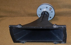
Attachments
For relatively low output use, mid cones can be eliminated using a coax HF.Concerning the crossover difficulties with a 1.4 inch Coax: Would it be possible to leave the cone mids out of the speaker and use just the woofer and coax, or even make a speaker similar to the SM60M with just the compression driver? BMS suggests a 300hz crossover, which should be in the area of the woofer crossover of the sh50. On the other hand, i have no clue how much of the "synergy" concept would be left in such a horn.
That said, even small cone drivers have far more displacement than the BMS coax drivers, horn loaded they can go far louder with less distortion at 300 Hz at a fraction of the cost.
Thanks Art: so for the mid horn in the CW its polar response will become wider in the vertical as frequency descends and will also become narrower at the same time in the horizontal plane? With system pattern being determined by the proximity between the mid horn and woofer operating as a combined system.
So looking back at my question to Tom then as a small horn attempts to play down to or just below cut off the polar response looses directivity is that correct? Thanks.
So looking back at my question to Tom then as a small horn attempts to play down to or just below cut off the polar response looses directivity is that correct? Thanks.
For relatively low output use, mid cones can be eliminated using a coax HF.
That said, even small cone drivers have far more displacement than the BMS coax drivers, horn loaded they can go far louder with less distortion at 300 Hz at a fraction of the cost.
Hi Art, part of this is not sitting right with me, and I am not quite sure how yet.
The cost part is right. I always assumed that most DIY synergy projects were done because it is cheaper to cobble together four small cones than to pay for the BMS, which mid range only is almost $600 stand alone.
But the BMS diaphragm is much more efficient than any paper cone that I know of. And I am not sure where they stack up harmonic distortion wise, but the BMS has lower IM distortion than cones, and to my ear is much more precise, and has better dynamics. In fact the BMS dual concentric is built for high output, and one drawback to using it for home hi-fi is that you will never come close to using its full output.
Tom (Hi Tom) is using three per side to fill huge stadiums with his largest (Is it a synergy, or something beyond?) horn cabinets.
My thought (disclaimer, I sell BMS) is the BMS is ideal for what he is asking. It will sound better (to my way of hearing). It will also be more expensive, and not be a synergy horn.
Regards, Jack
Anybody have a set of polars of the BMS coax units on a CD horn? I think that in itself would answer a lot of questions. Will be interesting to see how they do when the SEOS guys get their SEOS 24s.........
Anybody have a set of polars of the BMS coax units on a CD horn? I think that in itself would answer a lot of questions. Will be interesting to see how they do when the SEOS guys get their SEOS 24s.........
There used to be some polars of the 4594 on a 24" OS waveguide in this thread:
http://www.diyaudio.com/forums/multi-way/149085-testing-big-waveguide.html
Unfortunately the pictures are now gone, but I remember they looked good from 400 hz and up, though with some beaminess at the top end.
Edit: According to hulkss the trick to make a good crossover is to have some delay on the upper frequency diaphragm to have both diaphragms playing in phase.
Last edited:
Originally Posted by weltersys
For relatively low output use, mid cones can be eliminated using a coax HF.
That said, even small cone drivers have far more displacement than the BMS coax drivers, horn loaded they can go far louder with less distortion at 300 Hz at a fraction of the cost.
In the DSL JH-60 Tom "cobbles together" six 6 inch midrange cones (and six 18" cones) to keep up with the output of 3 of the BMS coax hi mid.
The crossover point between the cones and coax is probably much closer to 1000 Hz than 300 Hz, which makes a huge difference in excursion and distortion at high output levels.
The mid cones use only about 3 dB more power than the hi mid coax, the coax is not all that much more efficient than horn loaded mid cones.
The three coax high frequency diaphragms are really not up to the task of keeping up with the rest of the JH-90 at long distance due to air attenuation, so Tom came up with a layered combiner (after I goaded him😉) to put 64 little BMS (I think) drivers on one horn for those that want sparkly HF at 500 feet on hot dry days.
At any rate, relatively inexpensive cone drivers in an offset horn have far lower distortion at 300 Hz and far more output (therefore better dynamics) than the BMS coax drivers on a similar sized horn, it is simply a matter of displacement.
That does not negate the fact that the BMS coax on a large horn would be adequate in output at 300 Hz for most home applications, it just is not the most cost effective way to produce 300 Hz loud and clean.
But cone drivers don't just "bolt on" to a horn, there are some tricky little details that need to be worked out, so the BMS coax are a good choice for those that want good pattern control down to a fairly low frequency with a little less DIY.
Art
For relatively low output use, mid cones can be eliminated using a coax HF.
That said, even small cone drivers have far more displacement than the BMS coax drivers, horn loaded they can go far louder with less distortion at 300 Hz at a fraction of the cost.
Jack,Hi Art, part of this is not sitting right with me, and I am not quite sure how yet.
The cost part is right. I always assumed that most DIY synergy projects were done because it is cheaper to cobble together four small cones than to pay for the BMS, which mid range only is almost $600 stand alone.
But the BMS diaphragm is much more efficient than any paper cone that I know of. And I am not sure where they stack up harmonic distortion wise, but the BMS has lower IM distortion than cones, and to my ear is much more precise, and has better dynamics. In fact the BMS dual concentric is built for high output, and one drawback to using it for home hi-fi is that you will never come close to using its full output.
Tom (Hi Tom) is using three per side to fill huge stadiums with his largest (Is it a synergy, or something beyond?) horn cabinets.
My thought (disclaimer, I sell BMS) is the BMS is ideal for what he is asking. It will sound better (to my way of hearing). It will also be more expensive, and not be a synergy horn.
Regards, Jack
In the DSL JH-60 Tom "cobbles together" six 6 inch midrange cones (and six 18" cones) to keep up with the output of 3 of the BMS coax hi mid.
The crossover point between the cones and coax is probably much closer to 1000 Hz than 300 Hz, which makes a huge difference in excursion and distortion at high output levels.
The mid cones use only about 3 dB more power than the hi mid coax, the coax is not all that much more efficient than horn loaded mid cones.
The three coax high frequency diaphragms are really not up to the task of keeping up with the rest of the JH-90 at long distance due to air attenuation, so Tom came up with a layered combiner (after I goaded him😉) to put 64 little BMS (I think) drivers on one horn for those that want sparkly HF at 500 feet on hot dry days.
At any rate, relatively inexpensive cone drivers in an offset horn have far lower distortion at 300 Hz and far more output (therefore better dynamics) than the BMS coax drivers on a similar sized horn, it is simply a matter of displacement.
That does not negate the fact that the BMS coax on a large horn would be adequate in output at 300 Hz for most home applications, it just is not the most cost effective way to produce 300 Hz loud and clean.
But cone drivers don't just "bolt on" to a horn, there are some tricky little details that need to be worked out, so the BMS coax are a good choice for those that want good pattern control down to a fairly low frequency with a little less DIY.
Art
Last edited:
Originally Posted by weltersys
Tom "cobbles together"
Art
I said a DIY cobbles.
Tom never cobbles.
Neither does he use BMS coax drivers at 300 Hz, he uses cone drivers that have good output level with low distortion down that low 😉.Tom never cobbles.
at 300 Hz and far more output (therefore better dynamics) than the BMS coax drivers on a similar sized horn, it is simply a matter of displacement.
Art
You are right, thanks for the correction.
I meant the BMS has better transients than a cone.
On the BMS drivers (Hi Jack), I like these a lot because many radiate an expanding wavefront into the conical horns I use. This makes the acoustic path more like a continuous horn down to a small dimension and then what radiates is as much like a spherical patch as possible.
Best,
Tom Danley
Hi Tom, thanks for your post on the horn, and dispersion characteristics on frequency vs coupling distance. (mangled that) I remember your first post I read on this on the old LAB. Like a lot of your best posts for me it took me a bit to grasp it, because the concept was out of my reach at the time, but was described so well that it finally made sense. I wanted to wade in here, but am not as adept at describing it.
So, speaking of over my head. Would you go into more detail on the two sentences above. I am not picking up what you are laying down yet.
Thanks, Jack
I'm not Tom...
But consider the shape of the wavefront at the throat of the driver, where it enters the horn. Also consider it WRT frequency.
As mentioned before at high frequencies, if you start the wavefront out in a small section that is like an exponential horn's first few inches, those highs will continue out, truckin' into forward space, regardless of what the horn expands like. Thus a narrowing polar response WRT frequency.
Otoh, IF the drivers do NOT start with a narrow bit of throat (simplifying a bit, because the phase plug and what comes before counts) then the wavefront is "free" to expand to meet the expansion of the horn - which in Tom's case is a fixed conical section... thus he writes "...then what radiates is as much like a spherical patch as possible..."
What this last bit refers to is the idea that what comes out of the horn one might wish to be a section of a sphere (the wavefront is...) of some diameter. The section being as if cut out of a bubble by a cookie cutter.
So one would like the horn's wavefront (at all frequencies) to be equal in amplitude and equal WRT angle off axis - ie. a spherical patch.
Hope this is about correct.
(now I duck, in case I mucked it up...)
_-_-
- Status
- Not open for further replies.
- Home
- Loudspeakers
- Multi-Way
- Compression driver size and dispersion characteristics