Hopefully, we'll know in a couple of weeks! Just have to have the waveguide 3D-printed and the baffles CNCed...
SUPER PLANAR BLH with abrupt stepped expansion
I had some requests for SUPER PLANAR cabinets that could be used in a vehicle with high excursion drivers .... We needed something that was more forgiving in regards to T/S parameters (relative to the ROAR and standard Super Planar QWP) ....
Inspired by the use of a single abrupt expansion as seen in Martinsson's ROAR i decided to try applying that to our Super Planar model and voila it gave birth to a type of Super Planar that could properly accommodate some car audio style subs and produce fantastic performance!
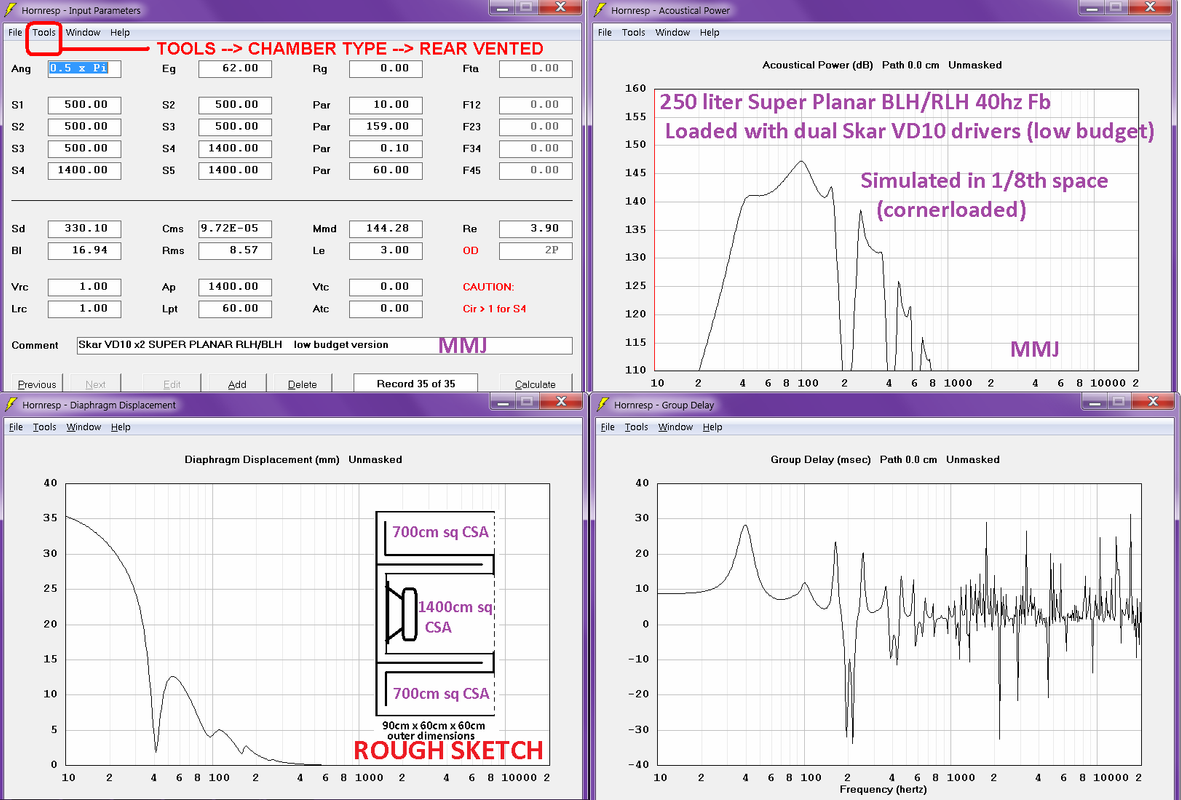
Below are a few Hornresp model collages and a few suggested folds (but there are many ways such a thing could be folded) , notice the extraordinary output from two budget drivers.... Low Group Delay, and excursion is well controlled.... .. .... These are simulated in .5 Pi (also called 1/8th space), we used this option since i was working on a model for usage in a vehicle and 1/8th space is as close as we can get to a vehicle's cabin gain or transfer function, though still very conservative, meaning output is still not just a tad conservative but completely understated from what i gather (compared to what we would really see in the cab of a car, truck, van or SUV etc ..)
NOTE: The Skar drivers would need to be measured to verify their T/S parameters .. I am just using their published parameters here as an example..
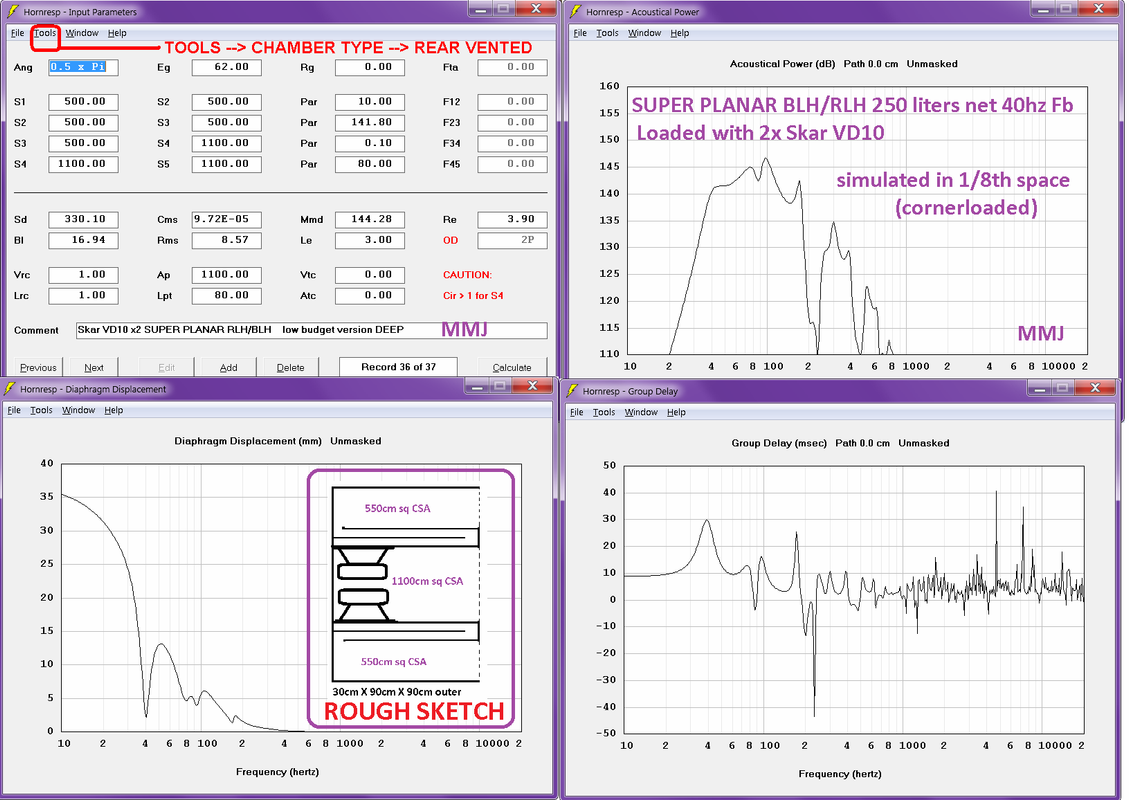
and below we have different dimensions, ...... 😀 and once again there are a variety of ways that such a design could be folded ... Going with a split-path is not entirely necessary even though that is what is being shown here ...... Can be built using all 90 degree angles like the ROAR and many of the classic Super Planar designs and some of the old ML-Transflex designs ..
NOTE:
I realize the mounting of the dual drivers in the rough sketch concept below is not entirely practical ...It is just an idea... . A different approach would be better ..
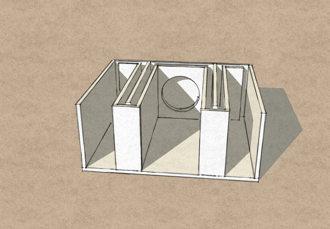
Here (below) is a lovely 3D sketch that our friend Dustin Morgan made for us and as you can see it is drawn for a single driver but if made almost twice as tall it could easily accommodate two drivers . .
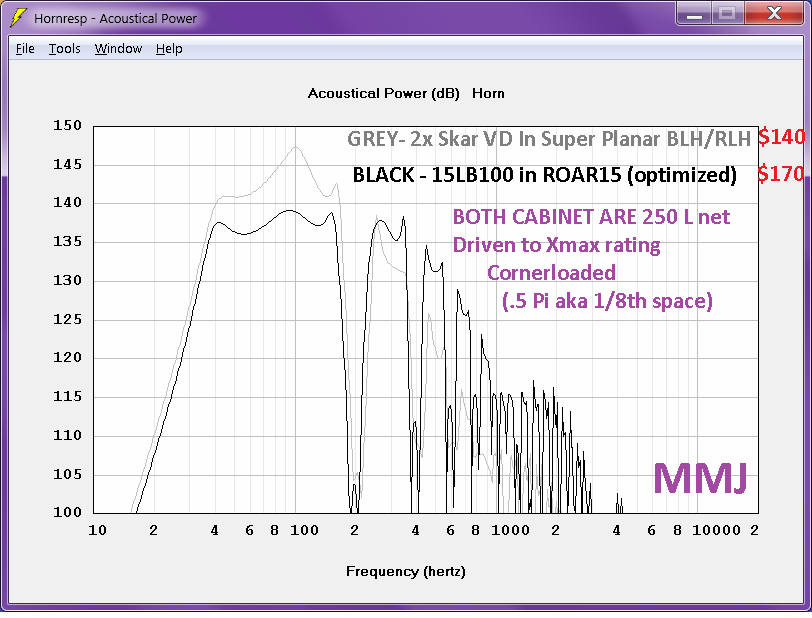
and here (below) shows the difference in output between the ROAR15 (custom optimized for the 15LB100 which is VERY hard to beat in terms of value) and this new Super Planar BLH-RLH (stepped) with dual Skar VD10 drivers ...... ............ The 1w sensitivity/efficiency (voltage adjusted to compensate for impedance) is actually very similar in these two cases and both are excellent performers but the Skars can handle more power before reaching their Xmax rating which allows them to have increased maximum theoretical output ....... ...................However, thermal power compression is not taken into account here and unfortunately that form of loss can be a big factor with these sorts of subwoofer drivers ....
In the next post i have another folding style to present . .
I had some requests for SUPER PLANAR cabinets that could be used in a vehicle with high excursion drivers .... We needed something that was more forgiving in regards to T/S parameters (relative to the ROAR and standard Super Planar QWP) ....
Inspired by the use of a single abrupt expansion as seen in Martinsson's ROAR i decided to try applying that to our Super Planar model and voila it gave birth to a type of Super Planar that could properly accommodate some car audio style subs and produce fantastic performance!
Below are a few Hornresp model collages and a few suggested folds (but there are many ways such a thing could be folded) , notice the extraordinary output from two budget drivers.... Low Group Delay, and excursion is well controlled.... .. .... These are simulated in .5 Pi (also called 1/8th space), we used this option since i was working on a model for usage in a vehicle and 1/8th space is as close as we can get to a vehicle's cabin gain or transfer function, though still very conservative, meaning output is still not just a tad conservative but completely understated from what i gather (compared to what we would really see in the cab of a car, truck, van or SUV etc ..)
NOTE: The Skar drivers would need to be measured to verify their T/S parameters .. I am just using their published parameters here as an example..
and below we have different dimensions, ...... 😀 and once again there are a variety of ways that such a design could be folded ... Going with a split-path is not entirely necessary even though that is what is being shown here ...... Can be built using all 90 degree angles like the ROAR and many of the classic Super Planar designs and some of the old ML-Transflex designs ..
NOTE:
I realize the mounting of the dual drivers in the rough sketch concept below is not entirely practical ...It is just an idea... . A different approach would be better ..
Here (below) is a lovely 3D sketch that our friend Dustin Morgan made for us and as you can see it is drawn for a single driver but if made almost twice as tall it could easily accommodate two drivers . .
An externally hosted image should be here but it was not working when we last tested it.
and here (below) shows the difference in output between the ROAR15 (custom optimized for the 15LB100 which is VERY hard to beat in terms of value) and this new Super Planar BLH-RLH (stepped) with dual Skar VD10 drivers ...... ............ The 1w sensitivity/efficiency (voltage adjusted to compensate for impedance) is actually very similar in these two cases and both are excellent performers but the Skars can handle more power before reaching their Xmax rating which allows them to have increased maximum theoretical output ....... ...................However, thermal power compression is not taken into account here and unfortunately that form of loss can be a big factor with these sorts of subwoofer drivers ....
In the next post i have another folding style to present . .
Last edited:
Inspired by the use of a single abrupt expansion as seen in Martinsson's ROAR i decided to try applying that to our Super Planar model
Wait until you hear what a large non-expanding quarter wave resonator can do. They seem to have a very aggressive and "hard" sound character with lots of tactile punch.
If you let the outer walls of the first simulated box extend another (342/200/4=) 42,75 cm you get a third resonator that will "fill" the deep suckout above the current passband.
Regards,
Johannes


I played with your frontresonator enhanced SUPERPLANAR idea. Since I use B&C 12PS100 I had to try those. This seems like a great idea. Very nice performance.
Black line is 2.0 Pi and grey line is 0.5 Pi radiation angle.
Regards,
Johannes
AWESOME
I am really looking forward to hearing one sometime 🙂
Johannes,
Haha , just extraordinary! I love the idea that we might be able to take this tech yet another step ...... I will need to figure out how to simulate the 42.75cm extension in Hornresp now ...
Wait until you hear what a large non-expanding quarter wave resonator can do. They seem to have a very aggressive and "hard" sound character with lots of tactile punch.
I am really looking forward to hearing one sometime 🙂
If you let the outer walls of the first simulated box extend another (342/200/4=) 42,75 cm you get a third resonator that will "fill" the deep suckout above the current passband.
Regards,
Johannes
Johannes,
Haha , just extraordinary!
I love the idea that we might be able to take this tech yet another step ...... I will need to figure out how to simulate the 42.75cm extension in Hornresp now ...
Last edited:
Very nice
That is an excellent looking Hornresp model with your 12PS100s Very efficient!
View attachment 634754
View attachment 634755
I played with your frontresonator enhanced SUPERPLANAR idea. Since I use B&C 12PS100 I had to try those. This seems like a great idea. Very nice performance.
Black line is 2.0 Pi and grey line is 0.5 Pi radiation angle.
Regards,
Johannes
That is an excellent looking Hornresp model with your 12PS100s
Very efficient!
Last edited:
Can you please sim 18LW2400 or Faital 18XL1600, for PA use? The large size should not be an issue, as long as we have a convenient form factor for stacking. Thanks in advance.
I will need to figure out how to simulate the 42.75cm extension in Hornresp now ...
I would build it as an add-on plywood collar.
I have been playing with an extra pipe mouth resonator section to fill in the deep suckout in different OD-QW loudspeakers we are building at the moment.


With an added section you get a smoother passband without the deep suckout. In the ROAR series I view the suckout as a good feature. In a backloaded OD-QW used as a fullrange loudspeaker it is a problem.


Regards,
Johannes
An externally hosted image should be here but it was not working when we last tested it.
An externally hosted image should be here but it was not working when we last tested it.
An externally hosted image should be here but it was not working when we last tested it.
How come you are not using the TH function to model this enclosure? There is no closed end to the enclosure.

I would prefer using the Compound Horn.
Very similar results.

Grey line is OD. Black line is CH.
Thats right
That is correct .... CH mode can be used if there is no driver offset whatsoever (as in the split-path arrangement) and in that case the model is simplified and easier to work with since there is no chamber type options or any Vrc/Lrc, Ap/Lpt to bother with .................... However, if there is some amount of driver offset like we might see in a non-split-path design then OD mode must be used, such as with the example i was going to show you guys next which has 20cm of driver-offset .. Splitting the path just wasn't an option in this situation due to the cabinet dimensions required and tuning desired, this was another car audio build request for some guys in Florida .... Features a heavy high-excursion 15" driver ... I am waiting on Dustin Morgan's 3D sketch to be finished before posting it here 🙂
Not that such a small amount of driver-offset makes a huge difference , it doesn't necessarily, but OD mode is flexible enough to simulate the design either way (offset driver or not) ....
That is correct .... CH mode can be used if there is no driver offset whatsoever (as in the split-path arrangement) and in that case the model is simplified and easier to work with since there is no chamber type options or any Vrc/Lrc, Ap/Lpt to bother with
.................... However, if there is some amount of driver offset like we might see in a non-split-path design then OD mode must be used, such as with the example i was going to show you guys next which has 20cm of driver-offset .. Splitting the path just wasn't an option in this situation due to the cabinet dimensions required and tuning desired, this was another car audio build request for some guys in Florida .... Features a heavy high-excursion 15" driver ... I am waiting on Dustin Morgan's 3D sketch to be finished before posting it here 🙂Not that such a small amount of driver-offset makes a huge difference
, it doesn't necessarily, but OD mode is flexible enough to simulate the design either way (offset driver or not) ....
Last edited:
Great options
Samuel ,
Those are both fantastic driver choices since they have sufficient motor force (BL^Re) and plenty of linear excursion and power handling ...............................
If i had to choose one or the other i would go for the Faital 18XL1600 for it's somewhat stronger motor force and edge in linear excursion (though the difference in excursion between the two drivers is not as stark as the published figures suggest because 18sound's formula for calculating linear excursion is more conservative than the formula used by Faital Pro)..
The 18LW2400 would feel right at home in a sub cabinet similar to the one featured at the lower portion of the post #1 , although for standard PA sub tunings i would go with a cabinet depth more in the 50" to 54" range and if your situation allows i would make the cabinet a few inches taller because when our first set was built we found that the driver was a very tight fit , meaning it would have been ideal to have a little more clearance behind the pole vent and in front of the cone (or to even have an angled baffle such as what is shown in one of the sketches)...
The 18LW2400 would also do well in a cabinet based on the folding styles shown in the first sketch at post #13
The Faital 18XL1600 on the other handwith it's stronger motor will prefer some reduction in CSA early in it's main path followed by expansion such as what is shown in the latter sketch at post #13 (link above) ... OR EVEN BETTER YET we could go with an expansion provided by an abrupt jump in CSA to form an additional useful quarterwave resonator such as used in Johannes and Martinsson's ROAR series designs and now also employed in the Super Planar BLH/RLH (stepped) design that we are currently exploring in group collaboration as of the last few days 🙂. It is so nice to have folks like Johannes, and GKH, Vansickle, and Dustin in Florida join in on this study (between DIYaudio and Facebook) 🙂.
With this single-step abrupt expansion in conjunction with the Super Planar design we are now juggling three different resonances (not including harmonics) and the output can be extraordinary! It is not just traditional compound loading but literally extra-compound loaded! 😀
Can you please sim 18LW2400 or Faital 18XL1600, for PA use? The large size should not be an issue, as long as we have a convenient form factor for stacking. Thanks in advance.
Samuel ,
Those are both fantastic driver choices since they have sufficient motor force (BL^Re) and plenty of linear excursion and power handling
............................... If i had to choose one or the other i would go for the Faital 18XL1600 for it's somewhat stronger motor force and edge in linear excursion (though the difference in excursion between the two drivers is not as stark as the published figures suggest because 18sound's formula for calculating linear excursion is more conservative than the formula used by Faital Pro)..
The 18LW2400 would feel right at home in a sub cabinet similar to the one featured at the lower portion of the post #1 , although for standard PA sub tunings i would go with a cabinet depth more in the 50" to 54" range and if your situation allows i would make the cabinet a few inches taller because when our first set was built we found that the driver was a very tight fit , meaning it would have been ideal to have a little more clearance behind the pole vent and in front of the cone (or to even have an angled baffle such as what is shown in one of the sketches)...
The 18LW2400 would also do well in a cabinet based on the folding styles shown in the first sketch at post #13
The Faital 18XL1600 on the other handwith it's stronger motor will prefer some reduction in CSA early in it's main path followed by expansion such as what is shown in the latter sketch at post #13 (link above) ... OR EVEN BETTER YET we could go with an expansion provided by an abrupt jump in CSA to form an additional useful quarterwave resonator such as used in Johannes and Martinsson's ROAR series designs and now also employed in the Super Planar BLH/RLH (stepped) design that we are currently exploring in group collaboration as of the last few days 🙂. It is so nice to have folks like Johannes, and GKH, Vansickle, and Dustin in Florida join in on this study (between DIYaudio and Facebook) 🙂.
With this single-step abrupt expansion in conjunction with the Super Planar design we are now juggling three different resonances (not including harmonics) and the output can be extraordinary!
It is not just traditional compound loading but literally extra-compound loaded! 😀
Last edited:
A Hornresp model that Samuel's Faital cabinet could be based upon
Ok guys, I have begun working on a Hornresp model for the Super Planar BLH/RLH (stepped) cabinet loaded with Faital 18XL1600 .... Initial main path CSA needs to be roughly 1000cm sq (or 500cm sq if a split-path) at 150cm length... The expanded CSA portion can be around 2000cm sq at 90cm length (for a total of 240cm path length)... The same 2000cm sq CSA for the vented "rear chamber" resonator (i sometimes call it the Front Chamber even though it is considered "rear chamber" in Hornresp) , and the length for this resonant chamber is 60cm ..... Although some of these figures are flexible the above numbers give our cabinet an internal volume of around 451 liters , which is reasonable for this level of performance 😎 .......
NOTE: If we choose to go with a split-path style folding then we can indeed model this in "CH" mode because there will be no driver-offset 🙂
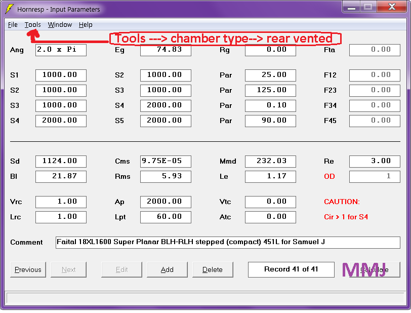
Stepping up the expanded CSA and resonator chamber CSA to 3000cm sq inflates the cabinet's net volume to over 600 liters once the path length is compensated to maintain a 40hz Fb, and the increase in efficiency & output are modest so i think we may have reached the point of diminishing returns at this size ..
Samuel, if you like this idea then the next step would be to figure out how to fold it and work out the dimensions ... Then you will have plans for your new cabinet!
Ok guys, I have begun working on a Hornresp model for the Super Planar BLH/RLH (stepped) cabinet loaded with Faital 18XL1600 .... Initial main path CSA needs to be roughly 1000cm sq (or 500cm sq if a split-path) at 150cm length... The expanded CSA portion can be around 2000cm sq at 90cm length (for a total of 240cm path length)... The same 2000cm sq CSA for the vented "rear chamber" resonator (i sometimes call it the Front Chamber even though it is considered "rear chamber" in Hornresp) , and the length for this resonant chamber is 60cm ..... Although some of these figures are flexible the above numbers give our cabinet an internal volume of around 451 liters , which is reasonable for this level of performance 😎 .......
NOTE: If we choose to go with a split-path style folding then we can indeed model this in "CH" mode because there will be no driver-offset 🙂
An externally hosted image should be here but it was not working when we last tested it.
Stepping up the expanded CSA and resonator chamber CSA to 3000cm sq inflates the cabinet's net volume to over 600 liters once the path length is compensated to maintain a 40hz Fb, and the increase in efficiency & output are modest so i think we may have reached the point of diminishing returns at this size ..
Samuel, if you like this idea then the next step would be to figure out how to fold it and work out the dimensions ... Then you will have plans for your new cabinet!
Last edited:
Thank you Mathew Morgan for your prompt reply and simulation.
Let me explain briefly:-
I am quite interested in the performance specs of Josh Ricci's Skhorn. So a cab with dual drivers like the Skhorn is fine.
I am looking at performance gains, better sound directivity and pattern, and lower weight if possible, as compared to Skhorn. My guess is that your design may score better in all these areas. Would like response down to 30Hz atleast, if not lower. So why not, if your unconventional designs can check all the boxes?
(P.S. Longest dimension should not exceed 54 inches; 60 inches might just be a little too much, both for handling and aethetics.)
Thanks in advance.
that we are currently exploring in group collaboration as of the last few days . It is so nice to have folks like Johannes
I want to encourage people to experiment with the front-resonator idea. We see a lot of "under the simulation" benefits with our ROAR designs that might be hard to quantify without extensive measurements.
I like your "SuperPlanar" idea, but I see some drawbacks with your early layouts compared to our ROAR designs.
Since the ROAR has the tapped pipe section exit into the front resonator symmetrical around the driver you get a very efficient cooling of the driver. The large differences in pressure and the pumping action of the tapped pipe and the very sudden area expansion just around the driver acts somewhat like acoustic cooling. If you put your hand very near the magnet and cone of the driver while running 100 watts or more through it you can easily feel an surprisingly efficient cooling centered on the magnet. It is not air-movement or just air blowing through the cooling canals in the driver. It feels like sticking you hand a static low temperature zone like a freezer.
I want to encourage you to go with the split path symmetrical layout. The pressures on the cone is pretty intense.

Here is the simulated driver diaphragm pressure with 3200 watts and 12,0 mm xmax in a ROAR18.
132,8 kg peak pressure is quite taxing for 240 grams of fiber-reinforced paper. Adding some cone warping asymmetry to this peak pressure will not help the working life span of the driver in any way.
Regards,
Johannes
As a side note I would like to add that 11587 Pa equals 175 dB sound pressure which puts it squarely into the non-linear acoustic domains of wave-steepening shock wave formation.
http://publications.lib.chalmers.se/records/fulltext/61697.pdf
😀
http://publications.lib.chalmers.se/records/fulltext/61697.pdf
😀
Forces
Johannes,
The thought of 130+ kilograms of weight being placed upon an 18" paper cone definitely does give me feelings of anxiety 😱 Yikes! Scary stuff, it really is amazing that we don't shred and blast apart cones more often with these high compression Tapped Horns and Front Loaded Horn designs that are so popular .....
Intuitively it does seem like the symmetrical split-path arrangement would provide a more evenly distributed pressure upon the cone and lend to longer driver survival rates in high compression situations ...... Seems like we should have a definitive answer on this by now since W-Bins have been around for decades , and even Mr Ercegovic's CYCLOPS design has been around for several years now... It would be great if someone could abuse an 18" driver in a CYCLOPS or a ROAR while at the same time abusing the same model driver in a standard 40hz Tapped Horn with the same compression ratio, until failure occurs.... This would verify that the symmetrical loading does indeed extend driver life as we suspect that it might ..... In turn it then may inspire designers to start employing symmetrical loading concepts in their work more often ..
In the case of the old 6th order Super Planar sub design shown in the lower portion of post #1 the compression ratio is very low on the main path (the LF tuned path) so i don't imagine that it makes much difference whether it is symmetrical or not, because the CR was less than 1:1 .... The forces being experienced by the cone in this situation are minuscule compared to a horn with 3:1 compression ratio , meaning we should be free and clear of the dangerzone🙂 This arrangement would work with Samuel's 18LW2400 ...
The Faital 18XL1600 on the other hand with it's stronger motor will prefer some compression so i will try to come up with a fold for it that uses the symmetrical split-path concept .... Perhaps just a scaled up version of the 3D sketch seen in post #143 , that layout should keep the outer dimensions within Samuel's requirements ...
Last edited:
Choosing the compromises
Samuel,
Keeping the depth at 54 inches would work well for your 18LW2400 in a 6th order Super Planar sub cabinet as shown in the latter part of Post #1 🙂
As i said before the dimensions on that cabinet are somewhat flexible ... I would suggest making it a bit taller and reducing the width by the same amount ... This will make it easier to fit the driver with plenty of clearance...
Samuel,
What sort of music do you typically listen to?
When designing an optimal system it is good to know what sort of extension is required to support the material you will be playing ... Play several of your favorite tracks through a spectrum analyzer or a software RTA in order to see where the low end energy stops or drops off in your music, and this is where we would want to have the cabinets tuned (even a few Hz above that, because our resonance has a useful width) .............. The reason i say this is because tuning lower than necessary just discards a great deal of efficiency, and power handling and performance , and often requires larger cabinets ...... So it is good rule of thumb to only tune exactly as low as you need to, and no lower, in order to maximize performance. 🙂 It is the reason why so many PA subs are tuned in the 35hz to 45hz range, it is considered a reasonable compromise between performance, extension and cabinet size ..
Samuel,
For your Faital 18XL1600 i would suggest one of the newer 8th order Super Planar BLH (stepped) cabinet concepts ...... Such as seen in the 3D sketch at post #143 .... I would need to optimize the CSAs and path lengths in order to come up with the dimensions for you .... The outer dimensions should easily stay within your requirements and the cabinet shape will be conducive to stable stacking and arraying 😀
Performance will be excellent as long as we aren't trying to tune too low ..
Let me know which option appeals to you the most (18LW2400 6th order or 18XL1600 custom 8th order) and we will get started 🙂
You are welcome Samuel! 🙂Thank you Mathew Morgan for your prompt reply and simulation.
I am looking at performance gains, better sound directivity and pattern, and lower weight if possible, as compared to Skhorn. My guess is that your design may score better in all these areas. Would like response down to 30Hz atleast, if not lower. So why not, if your unconventional designs can check all the boxes?
(P.S. Longest dimension should not exceed 54 inches; 60 inches might just be a little too much, both for handling and aethetics.)
Thanks in advance.
Samuel,
Keeping the depth at 54 inches would work well for your 18LW2400 in a 6th order Super Planar sub cabinet as shown in the latter part of Post #1 🙂
As i said before the dimensions on that cabinet are somewhat flexible ... I would suggest making it a bit taller and reducing the width by the same amount ... This will make it easier to fit the driver with plenty of clearance...
Samuel,
What sort of music do you typically listen to?
When designing an optimal system it is good to know what sort of extension is required to support the material you will be playing ... Play several of your favorite tracks through a spectrum analyzer or a software RTA in order to see where the low end energy stops or drops off in your music, and this is where we would want to have the cabinets tuned (even a few Hz above that, because our resonance has a useful width) .............. The reason i say this is because tuning lower than necessary just discards a great deal of efficiency, and power handling and performance , and often requires larger cabinets ...... So it is good rule of thumb to only tune exactly as low as you need to, and no lower, in order to maximize performance. 🙂 It is the reason why so many PA subs are tuned in the 35hz to 45hz range, it is considered a reasonable compromise between performance, extension and cabinet size ..
Samuel,
For your Faital 18XL1600 i would suggest one of the newer 8th order Super Planar BLH (stepped) cabinet concepts ...... Such as seen in the 3D sketch at post #143 .... I would need to optimize the CSAs and path lengths in order to come up with the dimensions for you .... The outer dimensions should easily stay within your requirements and the cabinet shape will be conducive to stable stacking and arraying 😀
Performance will be excellent as long as we aren't trying to tune too low ..
Let me know which option appeals to you the most (18LW2400 6th order or 18XL1600 custom 8th order) and we will get started 🙂
Last edited:
- Home
- Loudspeakers
- Subwoofers
- Compound loading 6th order quarterwave "Super Planar" horns and pipes concepts/builds