Hi all. I've been mulling over some of the problems inherent to building amplifiers, both tube and otherwise. I'm a believer in the P-P final stage as it requires much less perfection in an OPT. But I also think that if you "do" create a kind of perfection in a P-P OPT it deserves a final amplification stage that does it justice as far as efficiency and linearity. It would marry the best of both worlds.
I've lurked about these pages for many years absorbing information. It seems to me the kink in the get-a-along is that the P-P output stage isn't traditionally a long tail differential stage that can be used with a CCS. The reason for this is that the final stage is always the limiting factor for power and the slightest move into A2 amplification draws current into the grid circuit on the positive excursion of the input signal. That current draw upsets the balance of current draw between the two final tubes.
I'm just throwing this out there realizing it is a tough nut to crack. I haven't cracked it and am strictly thinking about this for my own audio pleasure. But I'm wondering how one would go about creating a circuit that would compensate for that unbalanced grid current draw? There seem to be so many benefits of this type of topology- including common noise rejection and elimination of DC current through the OPT, and allowing a low quality power supply except perhaps for the servo circuitry -that it is a no brainer to try to implement it. I know there are people who have cracked it. Allen Wright comes to mind. Do any circuit ideas come to mind to those technically oriented out there. Thanks in advance.
You could use a separate B+ supply for each side's cathode follower/mosfet follower grid driver. These would float, with negative sides connected to the cathodes. That way no A2 grid current goes thru the CCS tail. Same thing is sometimes done for g2 current to keep it out of the tail.
The simplest way is to just use a cap from each cathode, with a series resistor (or Gyrator) to the main B+ on each side. Each driver draws its B+ current from the top of the caps. The tail CCS then has to provide the usual tail current plus the average DC sum of the driver currents that way.
(the cap supplies the pulsed grid current supply, and the resistor or gyrator keeps tail current add-on to DC)
Last edited:
The whole point of PP is that it DOESN'T need to be class A, hence yielding more power. Putting a CCS in the cathode circuit cripples it, akin to tying two people together and chopping off half their legs, so they have to hop along on the single remaining tied-together pair.
Tim
Tim
"...that does it justice as far as efficiency and linearity."
I assume you are talking about triodes if you are worried about grid current. A differential(necessarily class A) triode output stage might do well as far as linearity goes, but efficiency will not be good.
Personally, I think you will spend a lot of effort and not have much improvement over an A2 push pull topology. It seems like it would just clean up some even harmonic distortions that there aren't much of and that won't sound that bad anyway. However, sometimes the payoff in learning makes it worth doing crazy things. Don't let me discourage that.
You could use a separate B+ supply for each side's cathode follower/mosfet follower grid driver. These would float, with negative sides connected to the cathodes. That way no A2 grid current goes thru the CCS tail. Same thing is sometimes done for g2 current to keep it out of the tail.
The simplest way is to just use a cap from each cathode, with a series resistor (or Gyrator) to the main B+ on each side. Each driver draws its B+ current from the top of the caps. The tail CCS then has to provide the usual tail current plus the average DC sum of the driver currents that way.
(the cap supplies the pulsed grid current supply, and the resistor or gyrator keeps tail current add-on to DC)
Very interesting and creative. I would never have thought of that way of implementing it. I think I'm understanding the basic principle but have a few questions. For the CCS to not have to supply the added DC on peaks wouldn't the gyrator have be supplied from "below" the CCS tail through the gyrator. It seems like otherwise the CCS would have to supply the additional current for large crescendos that last over many cycles. I think I understand that a capacitor could supply instantaneous current and might be attached at the cathode. I'm probably thinking about this wrong as its hard sometimes to visualize these things.
As far as this amp being efficient I have to admit my bad. It won't be efficient at all. It would really be an amp that would serve the same niche that single ended amps serve. It would be pure class A but without the problems that single ended amps have, i.e.
1. SE operates in the middle of the transfer characteristic but all individual tubes differ slightly on either side of the bias point.
2. None of the bad sacrifices that must be made to create a OPT for an SE amp.
3. And it would have the advantages I already said in my first post. (Of course, efficiency not being among them.😀)
Eric
As has been said here, what you are achieving is the best PP output stage. If your the sort of person who can live with the cost benefit analysis of SE then a class A PP stage is just the same - but better.
If you do decide to go down this path then take the opportunity to eliminate the airgap in the OT and so eliminate hysteresis within the core by going for a toroidal output transformer. The benefit comes in low level detail which is otherwise lost at crossover.
Most people are sold on the idea of the extra power achievable through PP and so there are almost no PP amps built with the same attention to detail and considerations applied to SE, I say go for it and live with the advantages and limitations of class A. You will be among a handful of people who have really tapped the full potential of a correctly implemented PP amp. By the way, as far as i am aware the Allen Wright Vacuum State amp doesn't operate in AB2. The other example of a fully class A PP amp is the Amnity.
Direct coupled or Interstage Transformers will give the best that PP has to offer. My current amp is a direct coupled pentode input stage shade 6AS7 differential output stage amp with a peak output of 7watts per channel (for about 120watts input). This is about the top of what can be achieved from PP.
Shoog
Very interesting and creative. I would never have thought of that way of implementing it. I think I'm understanding the basic principle but have a few questions. For the CCS to not have to supply the added DC on peaks wouldn't the gyrator have be supplied from "below" the CCS tail through the gyrator. It seems like otherwise the CCS would have to supply the additional current for large crescendos that last over many cycles. I think I understand that a capacitor could supply instantaneous current and might be attached at the cathode. I'm probably thinking about this wrong as its hard sometimes to visualize these things.
Eric
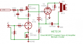
To keep grid current out of the cathode circuit requires that the gyrator supply current be returned to the cathode of the output tube. Here is a SE circuit to illustrate but you could do the same for each side of the P-P driver.
Smoking-amp's suggestion to use a cap returned to the output cathode instead of a whole isolated supply might be perfectly fine if the cap has a chance to recharge between grid current peaks. That's a clever solution that might work well for grid current that only flows during part of the cycle. If you have say a 50mA sine shaped peak that is say 20% duty cycle then you only need to supply on average about 7 or 8 mA over the driver idle current to keep the cap from discharging.
If you do use isolated supplies they can be dead simple because the gyrator filters out the noise and ripple. Mine use a tiny toroid, a bridge rectifier, and a single cap.
I'm planning to convert my 300B P-P class A monoblocks to from choke direct coupled drivers to gyrator direct coupled + A2 using this circuit. I might try the cap approach just to see how it works.
Cheers,
Michael
PS even though the extra grid current is returned to the output cathode, when you drive a tube into class A2 there is somewhat more asymmetry to the load line. IOW, there is more output swing when driving the grid (+) than when driving the grid (-). Your tail CCS will not allow this and force symmetry. There will be somewhat less output power than without the CCS tail and the harmonic signature will be different. But I guess that's what you're going for. It will be interesting to hear about your resullts.
Attachments
Last edited:
Michael's approach looks excellent. Can use a cheap floating power supply, Gyrator keeps out the noise, and the floating connection to the cathode keeps current out of the "tail".
--------------------------------
RE:
"For the CCS to not have to supply the added DC on peaks wouldn't the gyrator have be supplied from "below" the CCS tail through the gyrator. It seems like otherwise the CCS would have to supply the additional current for large crescendos that last over many cycles."
The non-floating pwr supply gyrator version smoothes out the current draw thru the tail to near DC (and being class A mode, it will have to draw enough steady current to cover the peaks pulled from the cap) so the tail CCS just needs up rating to cover it. The gyrator does have a time constant, which will interact with long crescendos, so the floating PS gyrator, like Michael's, is the best way (the long time constant then only affects the voltage on the driver drains then).
--------------------------------
RE: Tim:
"Putting a CCS in the cathode circuit cripples it, akin to tying two people together and chopping off half their legs, so they have to hop along on the single remaining tied-together pair."
and: Shoog:
"Most people are sold on the idea of the extra power achievable through PP and so there are almost no PP amps built with the same attention to detail and considerations applied to SE, I say go for it ..."
Tim has a point here, in that differential mode becomes more distorting at odd harmonics at large power levels (output stages), it does work well for small signal input stages. And efficiency goes to He.. with class A. Some fixup is possible with an optimum tail impedance to null the 3rd harmonic. Efficiency suffers with a CCS tail too, an inductor tail could remedy a little of that.
Shoog has a point here on class A P-P and attention to detail and avoiding crossover dist. But at a considerable cost in efficiency. Class AB1 can do quite well at avoiding crossover if done well (local Fdbks). The SS designers also do have a potent local Fdbk solution for avoiding crossover dist. in AB mode using "Hawksford error correction", which is never seen in tube designs (but was originally patented for a tube amp: Llewellyn). Not that hard to do really.
-------------------------------
For Class A2 or AB2, I would prefer avoiding operating in both the grid current and non grid current regions, where another crossover effect occurs. Keep an eye out for scaled g2,g1/Mu drive or whatever...drive threads coming soon. Interest is developing in this new approach, which can stay in grid current mode continuously, efficiently, safely and linearly. Even has enhanced power output capablility.
Don
--------------------------------
RE:
"For the CCS to not have to supply the added DC on peaks wouldn't the gyrator have be supplied from "below" the CCS tail through the gyrator. It seems like otherwise the CCS would have to supply the additional current for large crescendos that last over many cycles."
The non-floating pwr supply gyrator version smoothes out the current draw thru the tail to near DC (and being class A mode, it will have to draw enough steady current to cover the peaks pulled from the cap) so the tail CCS just needs up rating to cover it. The gyrator does have a time constant, which will interact with long crescendos, so the floating PS gyrator, like Michael's, is the best way (the long time constant then only affects the voltage on the driver drains then).
--------------------------------
RE: Tim:
"Putting a CCS in the cathode circuit cripples it, akin to tying two people together and chopping off half their legs, so they have to hop along on the single remaining tied-together pair."
and: Shoog:
"Most people are sold on the idea of the extra power achievable through PP and so there are almost no PP amps built with the same attention to detail and considerations applied to SE, I say go for it ..."
Tim has a point here, in that differential mode becomes more distorting at odd harmonics at large power levels (output stages), it does work well for small signal input stages. And efficiency goes to He.. with class A. Some fixup is possible with an optimum tail impedance to null the 3rd harmonic. Efficiency suffers with a CCS tail too, an inductor tail could remedy a little of that.
Shoog has a point here on class A P-P and attention to detail and avoiding crossover dist. But at a considerable cost in efficiency. Class AB1 can do quite well at avoiding crossover if done well (local Fdbks). The SS designers also do have a potent local Fdbk solution for avoiding crossover dist. in AB mode using "Hawksford error correction", which is never seen in tube designs (but was originally patented for a tube amp: Llewellyn). Not that hard to do really.
-------------------------------
For Class A2 or AB2, I would prefer avoiding operating in both the grid current and non grid current regions, where another crossover effect occurs. Keep an eye out for scaled g2,g1/Mu drive or whatever...drive threads coming soon. Interest is developing in this new approach, which can stay in grid current mode continuously, efficiently, safely and linearly. Even has enhanced power output capablility.
Don
Last edited:
For Class A2 or AB2, I would prefer avoiding operating in both the grid current and non grid current regions, where another crossover effect occurs. Keep an eye out for scaled g2,g1/Mu drive or whatever...drive threads coming soon. Interest is developing in this new approach, which can stay in grid current mode continuously, efficiently, safely and linearly. Even has enhanced power output capablility.
Don
I am intrigued by this idea, and have no idea how it would be implemented. I will hold fire on a fully balanced amp until I hear further. Perhaps you can give us a heads up on this thread as well as when another thread is started on this subject for those of us who don't keep up that much, but who get emails updates on threads we've already contributed to. Thanks much.
Eric
Last edited:
Allen Wright comes to mind.
C'mon Allen, dangle a carrot or two!!!
Hey, smoking amp
I read through most of relevant material about g2, g1/mu drive and got the gist of it. I think there is a lot of promise there. There seems to be several advantages, including more linearity, more power, and possibly eliminating a negative bias supply in the final stage. Of course you'd have to use cathode/source followers to drive it but that seems to be the best way to drive a final stage anyway - now you are just forced into it.
It seems to me that idea actually can be related to the original subject of this thread, a fully differential final stage. You are right that A2 amplification can be considered as having a potential for crossover distortion in its own right, separate from P_P crossover distortion without a CCS. Why not combine the two ideas? It seems to me with scaled drive on g2,g1 you could design a differential final stage that has a lot more power and gets rid of both types of crossover distortion.
Since one is using current to drive the final stage as well as voltage one it would seem that you could simply make a choice as to whether you placed the CCS on the followers that supply the current or in the traditional method of the CCS in the cathode circuit. Experiment and subjective listening tests could be the final arbiter. Just my 2 cents.
Eric
Take a look at this thread:
http://www.diyaudio.com/forums/tubes-valves/161112-what-tubes-tube-amp-2.html
Sounds like the Circlotron is what you are looking for. Operates easily in A2 and no worries of crossover distortions. I run grid current all the time- works great!
http://www.diyaudio.com/forums/tubes-valves/161112-what-tubes-tube-amp-2.html
Sounds like the Circlotron is what you are looking for. Operates easily in A2 and no worries of crossover distortions. I run grid current all the time- works great!
I received an 1625 push pull amp made by the DIY friend. He had some trouble to get it right. It employs two LM317 CCS at each leg of the 1625 and run it at 41mA with a 2000uF bypass capacitor. The 1625 is triode strapped.
I checked the output power of the amp was at 5Wrms. I was so curious having both LM317 joined together and remove the bypass caps. Then, it will form a differential output PP stage. Surprisingly, it produce 10Wrms after modified as differential.
I wonder why it gives more power with differential.
Johnny
Well, technically it can't give more power if the usual assumptions are in place. Usually when something like that happens one of three assumptions don't actually exist. The three assumptions:
1. The circuit is exactly like he described it to you when he gave it to you to work on.
Say, for instance it was operating higher in class A in the original implementation than either you or he thought. Perhaps the change you tried brought it lower into class A, as an example.
2. The circuit operates exactly the same both before and after your change except for the small change you introduced.
You fundamentally changed the circuit somehow in a way you didn't envision so it may not be exactly as you are describing it here. Not saying any mistakes were made but speaking from experience I know I've done that. You will have a lot of company.
3. All measurement are correct.
A mistake in measurement is taking place or some condition has changed to facilitate a measurement that was forgotten to be taken into account. Also sometimes conditions change between measurements that are forgotten.
Hope this helps. Its pretty hard to do remote troubleshooting. Maybe there are others here who can be more helpful.
Eric
- Status
- Not open for further replies.
- Home
- Amplifiers
- Tubes / Valves
- Completely differential amplifier final stage