Hi,
I've just finished a protection schematic for my audio system. Some circuits are my idea, others are found on the internet. The schematics are tested only in LTSpice so far. I want to know your opinion before I start building it.
It has the following features:
- 2.2s start delay
- disconnect speaker in 120ms after power down
- disconnect speaker in 50ms after 50V DC on amplifier output
- disconnect speaker in 100ms after 1MHz @ 3Vp on amplifier output
- disconnect speaker in 1...10ms after exceeding maximum current
- thermal shutdown with programmable temperature
- variable fan speed controlled by temperature
- clipping indicator
If you know other usefull fetures, please let me know.
Attachments
Hi,Hi,
I've just finished a protection schematic for my audio system. Some circuits are my idea, others are found on the internet. The schematics are tested only in LTSpice so far. I want to know your opinion before I start building it.
It has the following features:
- 2.2s start delay
- disconnect speaker in 120ms after power down
- disconnect speaker in 50ms after 50V DC on amplifier output
- disconnect speaker in 100ms after 1MHz @ 3Vp on amplifier output
- disconnect speaker in 1...10ms after exceeding maximum current
- thermal shutdown with programmable temperature
- variable fan speed controlled by temperature
- clipping indicator
If you know other usefull fetures, please let me know.
I must say quite an elaborate schematic. isnt 50VDC a bit too much for the speaker to handle? can it be customised to lower voltage amps?
It looks like this is a typo - looking at the schematic, I can see it will trip at much lower DC. However, positive and negative thresholds seem to be asymmetric - I would use a symmetric DC sensing circuit.
This kind of board could also provide the soft-start feature, performing inrush for the main PSU - you need 2 delays in this case - first one for inrush, second one for the speakers.
In fact, the schematic would be much simpler, if micro-controller would be used for handling the delays and alerts from the sensors. That's the way "21-st century" control boards series is arranged (designed by myself and Jeff Wilhelm) 😉
Thanks for the tip with the soft-start feature. 
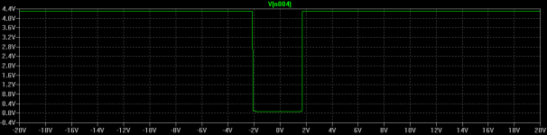
Of course, the DC detect circuit will trip at lower levels too, but a little bit slower: 250ms with 10V / 1.5s with 2.5V. I specified for 50V DC because when the amplifier crash, most likely it will output one of the power rails.
The thresholds are almost symmetrical: +1,7V and -2V.
I tried with a schottky instead of D4 and both tresholds are now 1,7V.
Attachments
Thanks for the tip with the soft-start feature.
Of course, the DC detect circuit will trip at lower levels too, but a little bit slower: 250ms with 10V / 1.5s with 2.5V. I specified for 50V DC because when the amplifier crash, most likely it will output one of the power rails.
The thresholds are almost symmetrical: +1,7V and -2V.
I tried with a schottky instead of D4 and both tresholds are now 1,7V.
OK - 1.7V in both directions - good 😎
Your DC detection should have the speakers disconnected long before output reaches 50V. At that point there's no voice coil left to save. Reaction at 2VDC is more important than 50VDC
I did a slightly lesser protection circuit using a PIC microcontroller.
I just look at the DC being there for 500mS and if it is the speaker relay is turned off.
I have a 3 second power up delay on the speaker relay.
The only thing lacking is over driving the speaker protection but in my systems I always have more powerful speakers than the amp could ever drive too hard.
The circuit using the PIC is minimal.
An externally hosted image should be here but it was not working when we last tested it.
Yes, but I don't like to use any microcontroller.
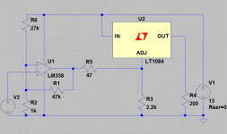
This one is analog with all needed amp and loudspeaker protection, and, this is a bonus, act as capacitor multiplier. It's based on JLH regulator for 80W mosfet amp, but with not fixed voltage regulation.
http://www.diyaudio.com/forums/solid-state/243481-200w-mosfet-cfa-amp-92.html#post4580606
@sajti,
It is similar to my circuit but it doesn't heave the feature to start the fan only at voltages that it spins, like 6V or more.
It is similar to my circuit but it doesn't heave the feature to start the fan only at voltages that it spins, like 6V or more.
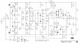
There are many schemes to protect amplifiers from both overload (output current limiters) and short circuits. With illiterate design, such circuits are often a source of distortion. The most effective are trigger protections that turn off the UN (voltage amplifier).
But such circuits do not protect the acoustic systems in case of failure of one of the arms of the output stage. For this purpose, circuits using relays are usually used, which, if chosen incorrectly, can also be a source of additional distortion.
For the attention of radio amateurs, a solution without a relay is offered. Field-effect transistors are used as keys in the power buses, and thyristors are used as triggers for fixing the state of the keys.
Attachments
Been 'doing' this Audio nonsense since 1967 DIy'd my first turntable in '68
Only referencing that I have been a full fledged Nutter for.. far Too long 🤣.
I have NEVER had speaker protection. Never perceived any need, Nor had any problems whatsoever.
And a Lot of gear has passed through in the last 5 or 6 decades.
Any electronics that featured turn on / off thumps or other extraneous / unpleasant noises ..were disposed of.. immediately.
Try it?
- Home
- Amplifiers
- Solid State
- Complete Amplifier and Loudspeaker Protection