Hi Heinz,
These are my numbers.
I switch compression off all the time, also with these numbers. The only difference is that I get these numbers with a simulation time of 10 cycles.
Normaly I use a simulation time equal to 5 cycles. But here I can't see a 2nd, 3th.... harmonics. Just like in post nr.91.
What do you mean by "Do first a test with Your inputsignal!"? Should I make the difference of the dB's from the input signal and the output signal at a certain frequency?
Do you think this is a good circuit? Because you're saying it could easily reach -180dB??
Thanks for the reply
Ben
Hi Ben
sorry for wrong name!
Set Your timestep m u c h smaller (one tenth from what You use now or even 100 times smaller!)
snip
What do you mean by "Do first a test with Your inputsignal!"?
Simply: "test" only Your inputsignal with FFT!
The noise-floor You should see there must be much lower than in Your FFT.
On this way You can test your simulations adjustments!!
snip
Do you think this is a good circuit?
I don`t look nearer to your circuit, the only thing what I notice is that Your FFT noisefloor is too high for the small harmonics that Your circuit produce and this depends only from a l l the things I told You.
snip
Because you're saying it could easily reach -180dB??
No I don`t belive; I mean the possible FFT noisefloor!
Regards
Heinz!
Hi Bensen,
your old graph showed +29 for signal and -34db for harmonic. The difference is 63db.
An harmonic at -63db is 0.07%, -83db is 0.007%.
your old graph showed +29 for signal and -34db for harmonic. The difference is 63db.
An harmonic at -63db is 0.07%, -83db is 0.007%.
Hi Andrew
Iàm sorry I don`t know what a WIKI is!
Also I write already all what one had to do to get a better resolution.
Use my above small example to play around : the best thing is always to make own experience.
Go to LinearTech website, load down SwCADiii, take my the example, cut of the ending "txt", open it with SwCADiii and try!
😉
Heinz!
Hi Power,
I have never written or edited a Wiki either.
It is the reference section on this forum where we can go to look for standard, often needed files/info/design/software/etc to help in our quest for successful DIY.
Your input on setting up your chosen sym package would be very useful to other users and it would save you having to repeat yourself.
BTW. I re-downloaded the current version of SWcad3 just yesterday. Maybe someday I'll learn how to import schematics and start using it. Now there's another Wiki topic!!
Hi Andrew,
thats fine! Than I recomment You to join this group:
http://groups.yahoo.com/group/LTspice
Iàm also there and had still to learn from them!
There are a lot of peoble that can (and will!) help You!
Also many examples You can get from there.
I do longer simulations but with my old simulator.
SwCADiii is also still new for me.
Regards
Heinz!
powerbecker said:Hi Ben
here is a small example.
Hi Heinz,
I really would like to work with that example. But when I want to run it, there appears an error window with:"MULTIPLE INSTANCE OF fLAG". Wat can I do to run this?
BTW: I've set the step time at:0.00000001s. I takes about three minutes to do a transient for 5 cycles. When I make an FFT now, this is as flat as can be, there are no harmonics to see. So there must be something wrong. So I hope I get your example to run.
Thanks
Ben
Hi Ben
"MULTIPLE INSTANCE OF fLAG"
sorry I don`t know what this means.
Recommend you simply "build" the same 2 parts circuit again in your simulator and use only my text and ".tran"-command for this 50Hz 10V source to do some experiments with this.
I have for test download my example and all is OK???!!
snip
BTW: I've set the step time at:0.00000001s. I takes about three minutes to do a transient for 5 cycles. When I make an FFT now, this is as flat as can be, there are no harmonics to see.
Thats small enough I think, May be the circuit is so good!?
How much difference You get between the signal and the floor?
Why not simulate both at the same time :
Input a n d Outputsignal of Your amp. Than do for both a FFT
Iàm shure there must be a difference.
Regards
Heinz!
Hi Ben,
snip
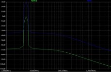
In the attachement you can see the FFT of the output signal and the input signal (green).
That looks strange for me!
Could this be really noise!??
How it looks if You do the same without a inputsignal: amp-input to ground!
Heinz!
snip
In the attachement you can see the FFT of the output signal and the input signal (green).
That looks strange for me!
Could this be really noise!??
How it looks if You do the same without a inputsignal: amp-input to ground!
Heinz!
Heinz,
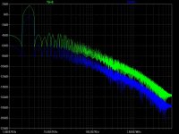
Here you have the FFT of output and input signal. Inpupt signal is connected to ground.
I stopped the sim after 20%, otherwise ist should taken over 30minutes to finish the sim. I don't know why it goes that slowly when input is connected to ground.
What looks strange to you in my previous post. What were you expecting? Can you describe it this? Maybe I can follow your way of thinking better than.
Sim:
Noise at output: +-240nV/Hz½.
Ben
Attachments

Ben,
honestly I must say that I not understand why in the FFT with input and outputsignal I find two "noisegrounds" and we can also see now in Your last FFT (without inputsignal) that noise is not the reason : floor is really low!.........
OK,
in this moment I do a simpel test here : One source and a divider to get two different signals and I also see "different-floors"!!
So again is the question why You can get not down for EG to -100dB!!???
Here I simulte 50Hz 10V and 0,9V with timestep 100ns!
For Your signal (5kHz) this this had to go proportional shorter!
May be You try a sim by deep freqencys to save time.
Now I "belive"(?) again that the timestep is too big.
Heinz!
Attachments

Heinz,
So, to your test it's logical I have to noise floor. But the noise floor is dependent on the frequency.
When I decrease my input frequency to 100Hz, the noise floor drops to about -90dB by 120kHz. And input frequency 50Hz--> -100dB by 120kHz.
Greetz
Ben
So, to your test it's logical I have to noise floor. But the noise floor is dependent on the frequency.
When I decrease my input frequency to 100Hz, the noise floor drops to about -90dB by 120kHz. And input frequency 50Hz--> -100dB by 120kHz.
Greetz
Ben
Hi Ben!
I had to assume Your timestep is still 10ns?
Then You had to reduce him linearly with increasing testfrequency
to get the same (deep) noisefloor.
So Your computer has something to work and You to wait but at least You should get a FFT-picture which shows you the harmonics You calculated already with ".four" command.
Heinz!
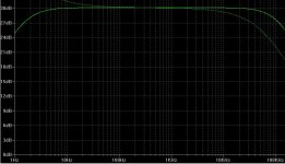
Can anybody tell me how I can determine the bandwidth of an amplifier. I know that OLG and bandwidth have direct influence on eachother.
Can I do this with an AC-analysis in LTspice? Do I have to read the highest frequency where there still is no decrease in gain.
For example: when the gain in my amp is 32dB, and the gain decreases from 10kHz--> the bandwidth is 10kHz? Or do I have to look at the -3dB point, to the frequency at 29dB?
And what are the normal values of bandwidth's in good quality amp's? I have here a schematic from elektor where the amp has an BW of 55kHz, but the OLG is only 2180x.
I'm experimenting with a complementary cascoded differential VAS, the OLG is about 13000x.
Greetz
Ben
- Status
- Not open for further replies.
- Home
- Amplifiers
- Solid State
- Complementary diff input with JFET and BJT cascode