That's effectively what he's doing. Hornresp uses lumped element modeling and can export models as Akabak2 LEM, and @3mb0t is modelling the interior chambers, ports and TLs in Akabak3 LEM. Only the exterior box and drivers are modelled in BEM. If the same model in being used, it also includes the floor for boundary coupling.

HR has only the possibility to add two ports (ME1 and ME2). I like the easy usability of HR. Even if akabak is harder to understand, you have this high degree of freedom. At the moment it is just not possible to simulate this configuration in HR. I don't get you, how would it be possible to get the right pipe size in HR?If you haven't, I think it's worth doing that simplified model in HR (even if you keep it to yourself). It wont help your directivity investigation, but it might aid your pipe sizing. FWIW.
The idea behind the TML was to reduce the impedance peak at fs 80hz of 25 ohm, so maybe no suction circuit is needed
an impedance peak is only an issue when it interacts with another impedance.
so for example when you build a passive crossover you linearize impedance using a notch filter and a zobel network ... but that is only needed because your driver has to work with the crossover which has its own impedance and it won't work right if the driver impedance isn't flat ...
when drivers are driven directly by a modern amplifier the impedance curve is almost irrelevant because modern amps have output impedance that approaches zero so there is no interaction.
as for line arrays there are conditions that need to be met for them to work right ... these are very difficult to meet which is why line arrays are generally not used unless there is some very specific reason why you want one. to give you a rough idea drivers must either be spaced closer than 1/2 wavelength at highest wavelength fed into them ( not possible in your case ) or the gaps between them should be not more than 80% of array length ( not possible with circular sources which are effectively shorter than their diameter ). so again, basically impossible in your case.
professional line arrays are built with special drivers that have square baskets for tighter spacing and special internal ( not visible from outside of speaker ) waveguides on tweeters that look like this:
these waveguides allow the array to meet the 80% requirement because they can be butted up flush against each other.
with line arrays it's all worth it if you can do it right and if you need their benefits of high SPL and tight pattern control. those are big IFs though.
this will probably be a great learning project for you but expect some serious response anomalies.
Last edited:
when drivers are driven directly by a modern amplifier the impedance curve is almost irrelevant because modern amps have output impedance that approaches zero so there is no interaction.
I didnt know, that modern amps dont have more work load at higher impedances. So older amps do? There are a lot of good "old" class A clones and valve amps do.
Meanwhile I have read a bit more about Line Arrays and know they should be used for what they are developed for, PA. Therefore I think there is a lot of snake oil in the HighEnd area and the "line array" build could not be optimal for a "perfect" sound in living rooms. It's like there are almost no real D'Appolito, although many claim to be.so again, basically impossible in your case.
You explained it really well and you're absolutely right 🙂. As you said, even if the design is optimized and the speaker sounds good, if I'm in the right spot in the room and don't move or maybe turn my head at the right moment when the sound changes, a true line array would never be the right design for a living room, as it wasn't designed for that. BUT, as you said, I'll learn a lot as long as I try it out or ask questions if I don't understand something.
Thanks for your input.
Most audio amps are designed to supply a voltage signal free of interaction with the speaker impedance. It's been this way for many years including valve amps.So older amps do?
If you have doubts you can try compensating the load to the amp. Some people report a slight difference in a small number of cases, for example near an upper midrange crossover peak.
An update after a while. In Akabak it is not possible to add damping to a waveguide but in ducts. So I changed the 3 wg by 9 ducts, each duct being proportionally smaller than the previous one to obtain a tempered line. To my delight, the f-response did not change. Then I try to change the values of the ducts and nothing happened. Therefor I have delete one duct by another. Shockingly the fr did not change significantly. Only when I was deleting the last duct (86mmx105mmx233mm) there was a clear change:

So the pink response is just 3 BR chambers with 3 chassis left. Here is the LEM with the last duct not deleted.

I try to understand if something is wrong with the LEM.
So the pink response is just 3 BR chambers with 3 chassis left. Here is the LEM with the last duct not deleted.
I try to understand if something is wrong with the LEM.
here is another version with all chassis in one chamber with 12liter and a port to the tml at 1/3 of the tml (length at ca. 920mm):

You might be better making the Akabak question into a new thread, since it is specialised knowledge.
@3mb0t Which model is being used ? if you DM the project to me, I can have a look at it.
The concept you are trying to build is inherently very tricky to tune because of all the interactions (bass reflex, transmission lines, HF combing). If you have modelling doubts, start by making it simple, like 9 drivers with their own individual sealed chambers, to verify the known monopole behavior. It will be easy to enable one driver at a time to incrementally see the effects when checking the model.
The concept you are trying to build is inherently very tricky to tune because of all the interactions (bass reflex, transmission lines, HF combing). If you have modelling doubts, start by making it simple, like 9 drivers with their own individual sealed chambers, to verify the known monopole behavior. It will be easy to enable one driver at a time to incrementally see the effects when checking the model.
Hi Allen, I dont think that is a akabak problem. I try a lot today and can tell, as DonVK sad, its an interaction between the systems (BR, TML, LA).You might be better making the Akabak question into a new thread, since it is specialised knowledge.
As you can see, I vary the concepts between: single big chamber, single small chamber with and w/o high pass (GHP), BR, simple TML, damping, different filters, different harmonic compensation (2nd, 3rd, 4th, 5th). Here are some FRs:
Also try, as you DonVK said, start simple from the start:
I can say, it is nice to see the different LF outcomes with different housings up to 600hz and its fun to see that complicated filters (that can be easily made with akabak) have the same output as simple closed or BR enclosures with enough volume. But, the -6db drop because of the line array could not be compensated w/o a change in enclosure design, an active push or a massive db loss between 100 and 5k hz.
Here is a screenshot from the rebuild session and what is left, w/o all the passive components 🙂 :
@DonVK:
Thank you for the offer to help, as I wrote, the main problem is the line array, that is not optimal for a linear FR 🙂
Overall thanks for all the response and input. It was fun and I have learned a lot about akabak and how to use it.
Two more points:
I also see that line arrays require special electrical treatment and are poorly suited for "normal" hi-fi, unlike public address systems. The sound will suffer. Line arrays are designed for specific situations and are well designed for them.
Secondly, compensating a transmission line makes almost no difference. It is more likely to have more problems.
Therefore, for a good speaker, it's worth investing more effort and money in selecting good chassis that fits into an easy-to-build enclosure. This is perhaps one reason why these cheap-looking JBL speakers are so popular in the high-end segment. 🙂
Greetings 3mb0t
If you want each chamber to excite the fundamental wave (to get deeper bass), the only way to do this is to apply DSP time delay so that each on excites the output fundamental to the maximum output at the right time when the max passes by the output slot. But this time delay will cause phase irregularities of the front wave and it will be all weird. I don’t think this can fundamentally be overcome.
I think you might want to use the full range drivers at what they are good for and use single rear sealed chamber as in typical tall line array. Add a 4 to 8 flat subwoofers in opposed push push orientation like KEF blade to provide bass. These would take up all the room on the side panels where the TL would otherwise be located. It would have much better bass and you separate the full ranges from having to move so much air so their distortion will be very low.
Maybe perhaps Dayton LW150-4-6 could work well here?

Sorry I am not seeing the TL for the array working here but I have modeled thousands of TL’s and line arrays and multi driver speakers and multi driver horn subwoofers with Akabak and IMO, the distributed nature of the excitation membranes spread along the length of a TL doesn’t work unless the time delay is applied to each driver.
I think you might want to use the full range drivers at what they are good for and use single rear sealed chamber as in typical tall line array. Add a 4 to 8 flat subwoofers in opposed push push orientation like KEF blade to provide bass. These would take up all the room on the side panels where the TL would otherwise be located. It would have much better bass and you separate the full ranges from having to move so much air so their distortion will be very low.
Maybe perhaps Dayton LW150-4-6 could work well here?
Sorry I am not seeing the TL for the array working here but I have modeled thousands of TL’s and line arrays and multi driver speakers and multi driver horn subwoofers with Akabak and IMO, the distributed nature of the excitation membranes spread along the length of a TL doesn’t work unless the time delay is applied to each driver.
Last edited:
Hey xrk971,
very good input. The LW150 would suit well in such a small enclosure. Nice one. I know the KEF Blade and like the design idea. 8 woofers maybe would match the rms power of the 9 drivers from the line array but that would be 600 watts in total 🙂 And it would not change the line array problem. Could work as a PA speaker.
The KEF Blade has just one coax chassis (point source) with sub support. You could say a C.A.S.T. coax and sub technology. 🤔
I think 4 woofers should do it. It would need another point source. I run already a sim with 8 LW150 and 4 PC83, maybe again with a coax like in the blade.
But it would be a totally different enclosure logic. Thank you
Last edited:
Another configuration suggestion, that would give you the look of small drivers in a LA. Similar electrical connection 3S3P as before, with 3 chambers in the enclosure. Just playing with some ideas 😀
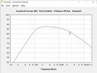
Chamber #1 holds 3 series drivers internally configured as a BP8 (see attached graph) for the low extension. The BP8 should have a 1st or 2nd order LP to match the next stage. It will not play very loud (95db) before hitting Xmax. The alternative is to EQ boost the LF but the same Xmax problem occurs. These drivers are hidden internally, with a single exit port.
Chamber #2 holds 3 series drivers in a small closed chamber to deliberately limit the low freq output (see attached graph). This would have a 1st or 2nd order LP before the next stage.
Chamber #3 holds 3 series driver, each in its own sub-chamber to minimize HF standing waves. Two drivers have a parallel RC shunt to bypass the driver as the frequency increases to reduce the combing from multiple drivers at HF. At some freq (say 7Khz) one driver (middle one) is primarily acting a the tweeter, the other 2 drivers at reduced levels.
Attachments

Last edited:
If you don’t need too much SPL, 4 drivers would work. 4 woofers in series parallel would get +6dB sensitivity at same impedance. There is a 10in version of the flat woofer but more expensive. More drivers may handle 600w but doesn’t mean you have to give it 600w. It still sounds better because cones move less and distortion is lower.
- Home
- Loudspeakers
- Multi-Way
- Compensated transmission line array