As promised in post #40, here is the simulation of my handwritten analysis...
I am using the HoneyBadger amp due to its popularity and its use of TMC compensation.
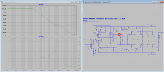
Screenshot_1: Shows the loop gain of the amplifier. The red square is the loop gain probe. As the handwritten analysis shows, it is single pole.
Screenshot_2: Shows the loop gain for OPS error voltage, what I call VE in the handwritten analysis. The red square is the loop gain probe. As the handwritten analysis shows, it is two pole.
With this, I have shown my analysis (handwritten doc also attached) and the simulation. I cannot show a 'lab result' since I do not own a HB amp nor the equipment to do the measurement (I don't own a network analyzer).
I am using the HoneyBadger amp due to its popularity and its use of TMC compensation.
Screenshot_1: Shows the loop gain of the amplifier. The red square is the loop gain probe. As the handwritten analysis shows, it is single pole.
Screenshot_2: Shows the loop gain for OPS error voltage, what I call VE in the handwritten analysis. The red square is the loop gain probe. As the handwritten analysis shows, it is two pole.
With this, I have shown my analysis (handwritten doc also attached) and the simulation. I cannot show a 'lab result' since I do not own a HB amp nor the equipment to do the measurement (I don't own a network analyzer).
Attachments

Last edited:
Can you show me a stand alone working TMC? I simulated that of dadod it is Tzzz.
I have seen absurd gadgets but this exceeds everything.
This is the circuit of your calculation.
I just simulated the HB amp, see post #41. Results agree with analysis.
I am unable to understand how someone pretending of engineering minded doesn't see the resistor and the capacitor are paralleled.
Iam trying very hard to accept 1+1=11
I have shown you in post #41 that '1'+'1' is indeed '11'.
(In many programming languages '+' is the concatenation operator, so '1'+'1' will give '11', where '1' is treated as a string and not a number due to the ' ' ... SQL is a good example).
With that, I am following my friend Dadod's footsteps and moving on to help others on other threads.
 [Out of this thread]
Last edited:
The first graph is the good one , and thank you posting it. It shows one pole compensation falling 6db/octave before the undesired second pole starts at high frequencies, you finaly showed, TMS is a single pole. The second graph is done by breaking the feedback resistor, and you commit the same error as your friend dadod.
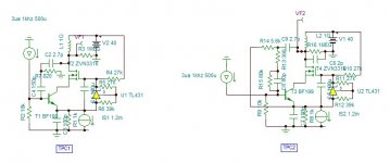
In your circuit ,the input current source flows it's current thru C1 because, voltage in, current out, element is very high impedance. By this you do not calculate the current ,If, as you do, it is the input , but the voltage that the input current developesby C1 + R//C2 along the feedback . There you could see the circuit if it has -Gm would be an integrator instead of an oscillator actually, but certainly not a two pole low pass.
Hayk
Last edited:
Hi LKA, so let me start with making sure I get the acronyms:
TMIC: Transitional Miller Input Compensation
TMC: Transitional Miller Compensation (The one in Bob Cordell's book)
MIC: Miller inclusive compensation (The one that some call Cherry)
MC: Miller compensation
Questions:
- Do you have a good resource that describes TMIC?
- Given you tried TMC, did you try TPC (two pole compensation)?
I am interested to see how TMC, TPC and TMIC stack against each other.
Thanks!
Hi, unfortunately I don't know any good TMIC resources. Cordell has only few words in his book. Mostly I use this kind of compensation in CFA amps.
Cherry is not MIC.
MIC: VAS output to IPS input
Cherry: OPS output to VAS input
Summery
Analysis of different types of 2 pole compensation ,showed only the TPC , to be 2nd order bandwidth widener. The other types bear 2 pole title for other reasons. Dadod's OITPC , maybe, can provide a phase advance. I have in TPC2 resistor R13 does the same.

The TMC transitional Miller compensation is first order 6db/ octave. A Cherry compensation at low frequencies and Miller at High. The story doesn't tell us why not 100% Cherry ?If stability is a problem , a series resistor along the Cherry capacitor is enough.
The Cherry NDFL is not 2 pole compensation , but a 2 pole feedback. Only frequencies bellow 200khz are feedbacked from the output, by this the second pole of the output stage is eliminated from the feedback loop. TMIC is also a 2 pole feedback but more subtle technique.
As I am hot on poles, my next thread will be the 2 pole feedbacks.
See you soon.
Hayk
Analysis of different types of 2 pole compensation ,showed only the TPC , to be 2nd order bandwidth widener. The other types bear 2 pole title for other reasons. Dadod's OITPC , maybe, can provide a phase advance. I have in TPC2 resistor R13 does the same.
The TMC transitional Miller compensation is first order 6db/ octave. A Cherry compensation at low frequencies and Miller at High. The story doesn't tell us why not 100% Cherry ?If stability is a problem , a series resistor along the Cherry capacitor is enough.
The Cherry NDFL is not 2 pole compensation , but a 2 pole feedback. Only frequencies bellow 200khz are feedbacked from the output, by this the second pole of the output stage is eliminated from the feedback loop. TMIC is also a 2 pole feedback but more subtle technique.
As I am hot on poles, my next thread will be the 2 pole feedbacks.
See you soon.
Hayk
Attachments
Last edited:
The TMC transitional Miller compensation is first order 6db/ octave.
Hayk
Pure nonsense
S
Why should an interesting thread be closed?
I'm just preparing different views on the topic, with also some non technical additions on the subject.
But first a more basic question:
In an earlier posting in this thread, some properties were given for an ideal VAS ( Voltage Amplifier Stage).
On of them being an infinite output impedance, in that case meaning that it should be a voltage to current converter.
However this current is converted into a voltage through the varying and moderately defined input impedance of the OPS depending on Hfe's and its load, unless a fixed resistor is used to set the gain independent of the OPS.
Despite loosing OL gain by inserting this resistor, it acts at the same time as local feedback around the VAS, thereby reducing overall THD and nihilating the loss in OL gain by letting the VAS act as a voltage to voltage converter.
So in each of the above situations, the VAS converts voltage to voltage, so why not take a voltage to voltage converter for the VAS with a low output impedance in the first place, thereby becoming almost independent on the OPS properties and its varying load.
That's why I am in preparation of two examples, one with a traditional high output impedance voltage to current VAS and one with a low output impedance voltage to voltage VAS.
In both topologies I want to show the effect of Single pole feedback, TPC and TMC, with some surprising results.
But give me some time to do all the work.
Hans
I started this thread to compare different types of 2 pole compensation. It revealed that there is only one type, the TPC. The reason of the thread is invalided.
To discuss about VAS stage you can post it here
Comparative VAS+cascode stage
Hayk
To discuss about VAS stage you can post it here
Comparative VAS+cascode stage
Hayk
That's why I am in preparation of two examples, one with a traditional high output impedance voltage to current VAS and one with a low output impedance voltage to voltage VAS.
In both topologies I want to show the effect of Single pole feedback, TPC and TMC, with some surprising results.
But give me some time to do all the work.
Hans
Hi Hans
What kind of OPS are you going to use in your simulations?
Stein
I started this thread to compare different types of 2 pole compensation. It revealed that there is only one type, the TPC. The reason of the thread is invalided.
To discuss about VAS stage you can post it here
Comparative VAS+cascode stage
Hayk
Hayk,
Altough my objective was to compare TMC and TPC in different topologies, I will start my own thread when ready.
Wish you all the best,
Hans
- Home
- Amplifiers
- Solid State
- Comparison Of 2 Pole Compensations