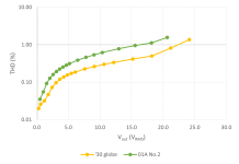
I have long wanted to compare the measured performance of the '01A and '30 and so built a wee test circuit. Obedient to the data sheets, each device-under-test is cathode biased at 9V and 3mA (cathode resistor fully bypassed with a 100μF non-polar electrolytic capacitor) with plate voltage of 135V (or close to).
The anode load is a Hammond 156C choke, nominally 150H and 3700Ω DCR (though mine measure 3200Ω). Atop the choke is a 5591 pentode (the Ericsson version of the WE403B, made under license) configured in BestPentode mode (a screen cascode using a high voltage BJT, the MPSA44A) that acts as a quasi constant current source and draws 10.5mA. Of that, 3mA passes through the ‘01A or ’30 (as the case may be) with the other 7.5mA passing to ground via resistors. The output is taken from the cathode of the pentode in quasi cathode follower mode, with measured output impedance in the order of 1.8kΩ. The circuit is a variation on Alan Kimmel’s choke assisted mu-stage, as written up in Vacuum Tube Valley (I forget which issue) with assistance from John Atkinson.
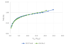
I used the circuit to test 14x'30s and 6x'01As (these numbers do not include the duds that were excluded from testing).
Included in the tests were four ‘30s in S-14 globe bulbs (the other 10 were in ST-14 small-shouldered bulbs). Of the four globe '30s, two behaved just like typical ST ‘30s while two were very low distortion devices. Very low ….
I've not yet listened to the circuit to compare the '01A and '30 and am interested in the experiences of any folk who have listened to both devices.
The anode load is a Hammond 156C choke, nominally 150H and 3700Ω DCR (though mine measure 3200Ω). Atop the choke is a 5591 pentode (the Ericsson version of the WE403B, made under license) configured in BestPentode mode (a screen cascode using a high voltage BJT, the MPSA44A) that acts as a quasi constant current source and draws 10.5mA. Of that, 3mA passes through the ‘01A or ’30 (as the case may be) with the other 7.5mA passing to ground via resistors. The output is taken from the cathode of the pentode in quasi cathode follower mode, with measured output impedance in the order of 1.8kΩ. The circuit is a variation on Alan Kimmel’s choke assisted mu-stage, as written up in Vacuum Tube Valley (I forget which issue) with assistance from John Atkinson.
I used the circuit to test 14x'30s and 6x'01As (these numbers do not include the duds that were excluded from testing).
- All filaments/heaters were powered by sealed lead acid batteries.
- The high voltage supply was an HP6209B, with additional C-L-C filtering.
- Output voltages and THD were measured with a Keithley 2015-P DMM, which also provided the low distortion 1kHz test signal.
Included in the tests were four ‘30s in S-14 globe bulbs (the other 10 were in ST-14 small-shouldered bulbs). Of the four globe '30s, two behaved just like typical ST ‘30s while two were very low distortion devices. Very low ….
I've not yet listened to the circuit to compare the '01A and '30 and am interested in the experiences of any folk who have listened to both devices.
Attachments

Pls send me the data sets or plot on a log-log graph, Check if they follow some kind of law. THX. 👍
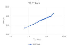
Well-spotted 🙂 The log-log chart attached is for a typical '30 in the ST-14 bulb. Discarding the two data points with highest THD and output voltage, the rest fall on a very straight line. Analytically:

For most '30 and '01A valves tested, c=1.25 calculating using logs in base 10. Using natural logs in base e , c=2.75 for most valves tested.
For the pair of low-distortion globe '30s, calculating with logs in base 10 gives c=1.55
For most '30 and '01A valves tested, c=1.25 calculating using logs in base 10. Using natural logs in base e , c=2.75 for most valves tested.
For the pair of low-distortion globe '30s, calculating with logs in base 10 gives c=1.55
Attachments
In my experience, 01A and 30 both sound good, but they have different flavors. 30 may be terribly microphonic when used as driver or preamp tube. Not surprising given its flimsy filament, 30 was primarily intended as Class B output tube in battery receivers.
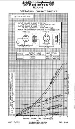
I guess that some circuits may have used the '30 in class B though maybe not too many since RCA produced the type 19 for that job. Here is the '30 in 1933 driving the 19 in class B.30 was primarily intended as Class B output tube in battery receivers.
Attachments
If you really want to test the 30 or the 01A you should take the output from its plate. The test above is the distortion of that hybrid mu-follower. It is possible that you could get lower distortion out of the plate output. IME, the mu-follower type circuit has an optimal load range for lowest distortion that is not necessarily the highest possible value. It could be much lower than one could assume.
Last edited:
Thanks, jhstewart9 - I hadn't looked at the TungSol data sheets before and, just as sser2 says, there is class B operation plain to see. 😳
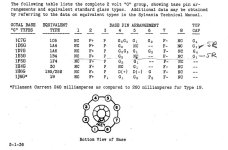
And it's reasonable to think that the octal 1H4G in the ST-12 bottle is likely to behave much like the 4-pin '30 in the ST-12 bottle - the stem, heater suspension and mica supports look very similar and I may yet take the 4-pin base out of the test circuit and replace it with an octal base to test a few 1H4Gs by way of comparison. I have attached a table of pre-octal valves (including the '30) re-based as octal and registered by Sylvania in 1936 that may be of interest to other experimenters.
I agree, 45, there are circuits that get closer to the inherent distortion of the '01A, such as Ale Moglia's arrangements for the '01A (here: https://www.bartola.co.uk/valves/2014/12/27/01a-preamp-build-part-5/) that show distortion an order of magnitude lower than I recorded. The comparative data from my wee experiment leads me to think that results similar to those Ale achieved with the '01A might be able to be achieved with the '30, with the usual caveats:
- there is certainly some variation valve-to-valve;
- the 01A's thoriated tungsten filament and the '30s oxide-coated filament may generate different noise spectra that might overlay distortion measurements at low levels and low frequencies; and
- ditto for microphonic behaviour.
Attachments
I used Type 30 tube in a line preamplifier and it is very very sensitive to microphonics, euphonics etc. I tried filament bias with Rod Coleman regulators and in that arrangement it was relatively OK, but I dropped it and I went for Telefunken RE084 instead. Much better tube than Type 30.
Lots of good information here, thanks for sending this. I saved that 4 pin to octal pdf. How does the Kimmel choke assisted circuit compare to the mu follower, performance wise? I read that article while researching the mu follower and thought about it. Maybe next.
How does the Kimmel choke assisted circuit compare
I can't say as I didn't do a direct comparision.
I've used both and 01A is a clear favourite on sound quality. I'd use a resistor load rather than the 156C. Tried both.
Be aware the 30 Special with double the filament current isn't particularly microphonic so very usable.
The 01A is difficult to implement, and Ale's gyrator is a known solution with many builds.
I tend to use the 2P29L or 112A for a low filament current tube.
Be aware the 30 Special with double the filament current isn't particularly microphonic so very usable.
The 01A is difficult to implement, and Ale's gyrator is a known solution with many builds.
I tend to use the 2P29L or 112A for a low filament current tube.
Thank you all for your impressions of both valves.
Reading as widely as I can, it appears that both valves can be microphonic. As to the causes, there are differences of opinion. Cunningham in 1954 in the RCA Review identifies the filament as the chief culprit (“Practical Considerations in the Design of Low-Microphonic Tubes”, in RCA Review, Volume 15, Number 4, pp.563-580) while Dagpunar presents photographic evidence showing that it could easily be any part of the valve (“Valve Microphony”, in Mullard Technical Communications, Number 61, pp.1-2.).
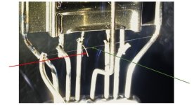
To get a better handle on the matter, I removed the glass from a dud '01A and a dud '30. Both filaments were "V" shape, suspended by a hook at the top and were similar in length (approximately 54mm for the ‘01A and 48mm for the ’30) and diameter. In the centre of the image below can be seen the silvery filament removed from the ‘01A (green arrow) laid across the pale remnant of the filament of the type ’30 (red arrow).
Reading as widely as I can, it appears that both valves can be microphonic. As to the causes, there are differences of opinion. Cunningham in 1954 in the RCA Review identifies the filament as the chief culprit (“Practical Considerations in the Design of Low-Microphonic Tubes”, in RCA Review, Volume 15, Number 4, pp.563-580) while Dagpunar presents photographic evidence showing that it could easily be any part of the valve (“Valve Microphony”, in Mullard Technical Communications, Number 61, pp.1-2.).
To get a better handle on the matter, I removed the glass from a dud '01A and a dud '30. Both filaments were "V" shape, suspended by a hook at the top and were similar in length (approximately 54mm for the ‘01A and 48mm for the ’30) and diameter. In the centre of the image below can be seen the silvery filament removed from the ‘01A (green arrow) laid across the pale remnant of the filament of the type ’30 (red arrow).
Attachments
It is worth considering that the filaments alone do not determine microphonic output:
- Viewed from above, the control grids of both valves spiral around their respective filaments in a flattened oval or “race-track” profile.
- The ‘30’s “race-track” is narrower than the ‘01A’s – it is 1.35mm at its widest compared to 2.30mm for the 01A, so that the ‘30’s filament is closer to its control grid than is the ‘01A’s.
- Both types’ grid and filament are enclosed by anode plates, spaced wider for the ‘01A (6mm) than the ’30 (4mm).
Last edited:
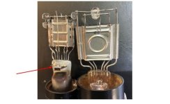
The '30 that I opened included a potential resonant structure in the form of a small getter tray (see the red arrow in the attached image) welded by a connecting rod to the ‘30’s left-hand anode supporting rod near the top of the stem. The tray is cantilevered and is a prime candidate for resonance – in which case it would vibrate the anode and other electrodes. While the getter tray may (or may not) be present in other type ’30’s, it is not present in the type ‘01A which uses other means of gettering.
Mitigating against the effect of the '30's getter tray are the mica insulators at the top of the ‘30’s electrode structure which press up against the inside of the shoulders of the ST-14 envelope, limiting the amplitude of vibration while tending to raise resonant frequencies. By contrast, all the electronic elements in early valves like the ‘01A and the S-14 globe bulb ’30 “sprout” from a cantilevered glass stem rising from the base. In the case of the ‘01A, the cantilevered stem stands free, enclosed by its glass envelope and free to resonate unconstrained like a tuning fork.
Mitigating against the effect of the '30's getter tray are the mica insulators at the top of the ‘30’s electrode structure which press up against the inside of the shoulders of the ST-14 envelope, limiting the amplitude of vibration while tending to raise resonant frequencies. By contrast, all the electronic elements in early valves like the ‘01A and the S-14 globe bulb ’30 “sprout” from a cantilevered glass stem rising from the base. In the case of the ‘01A, the cantilevered stem stands free, enclosed by its glass envelope and free to resonate unconstrained like a tuning fork.
Attachments
Last edited:
Of course, the most effective remedy for microphony is to ensure that valves are not subject to or are mechanically isolated from vibration. However, this is not always practical: Dagpunar found that microphony is inconsistent and mitigation of vibration can be difficult to achieve, since:
Since application and construction are integral to microphonic performance, I find it difficult to make general statements about the likely microphony of one valve type compared to another in any given application, especially on the basis of a sample of two valves cracked open for a look inside. Maybe that's just a posh way of saying that the '01A and '30 look like good, low-distortion devices worthy of use in audio - and that in your set up, Your Mileage May Vary🙂
…the chassis, cabinet or other structural members of the equipment have many different resonant frequencies for acoustical and mechanical vibrations, and the whole structure behaves as a combination of mutually coupled resonators. Consequently a small structural change in the equipment can completely alter the frequency spectrum of the acceleration of the valve.
Since application and construction are integral to microphonic performance, I find it difficult to make general statements about the likely microphony of one valve type compared to another in any given application, especially on the basis of a sample of two valves cracked open for a look inside. Maybe that's just a posh way of saying that the '01A and '30 look like good, low-distortion devices worthy of use in audio - and that in your set up, Your Mileage May Vary🙂
- Home
- Amplifiers
- Tubes / Valves
- Comparing the '01A and '30 - THD vs Vout