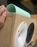
Hi all, I'm writing a post to share my ongoing project. I've printed one of @augerpro's waveguides and although my print is rough, the sound is good. The project is a box with about 0.35 cubic feet net. My goal is to create something that can serve as a compact wall-mounted speaker for use in home theater, so I want this to be capable of significant clean output. I want it to be a shallow depth wall mount that's able to be mounted in-wall for minimal front wall boundary issues. The prototype is 12" wide, 16.5" tall, and 6" deep with 3/4" plywood construction with a single brace spanning from to back at the position between the waveguide and woofer. Denim insulation lines most of the interior, Here's a picture as it stands now:

I have the crossover set to 1500hz LR4, there's a Linkwitz transform on the woofer, a 40hz second order highpass, five bands of global parametric EQ, three parameteric EQ filters on both the tweeter and the woofer. I will need to take better measurements before I try to translate this to a passive crossover, but I think it sounds decent right now.
After developing a crossover in MiniDSP I wanted to check how well it could produce higher sound pressure levels. I set the prototype in home theater center channel position and ran sweeps with the microphone in the MLP, a little less than three meters away. The amplifier I used was a home build Hypex UCD180, with one channel for the woofer and one for the tweeter.

Stacking these traces on top of each other, this is what I see for variation:

I'd love to know the proper way to calculate and display compression, so if there's a convention on how to do that in REW, I'm all ears.
Anyway, as a point of comparison I repeated this with a DIYSG HT8 to similar SPL and generated this:

I am presently using the HT8 as a center channel and I don't really notice distortion or compression during movies from this speaker. I do however notice some distress from the JBL LSR308, which are my left and right channels right now, and I moved one to the center position and generated this:

So it does seem that the sealed prototype is doing well in comparison. Here are two views of the distortion on the loudest trace of the sealed prototype:


Again, this was over 90db at over two meters, so I think this is a decent result. What I'm not sure about is the distortion in the ~200-600hz range. What could this be, just a limitation of the woofer?
My plans for upcoming development are:
-CNC a wood baffle to replace the 3D print. This is for looks and durability, and should rule out flex related distortion and issues from not flush mounting
-Collect gated measurements at two meters at five degree increments
-Measure impedances in-box with DATS
-See how close I can get to DSP filters passively
Overall I'm really liking the RS225-4 as a woofer. If I push it really hard with a low frequency sine wave I hear some wind noise around the phase plug, but I don't think that's a very realistic signal compared to music or movies.
Thanks for reading, if you have any questions or suggestions I'd love to hear them!
I have the crossover set to 1500hz LR4, there's a Linkwitz transform on the woofer, a 40hz second order highpass, five bands of global parametric EQ, three parameteric EQ filters on both the tweeter and the woofer. I will need to take better measurements before I try to translate this to a passive crossover, but I think it sounds decent right now.
After developing a crossover in MiniDSP I wanted to check how well it could produce higher sound pressure levels. I set the prototype in home theater center channel position and ran sweeps with the microphone in the MLP, a little less than three meters away. The amplifier I used was a home build Hypex UCD180, with one channel for the woofer and one for the tweeter.
Stacking these traces on top of each other, this is what I see for variation:
I'd love to know the proper way to calculate and display compression, so if there's a convention on how to do that in REW, I'm all ears.
Anyway, as a point of comparison I repeated this with a DIYSG HT8 to similar SPL and generated this:
I am presently using the HT8 as a center channel and I don't really notice distortion or compression during movies from this speaker. I do however notice some distress from the JBL LSR308, which are my left and right channels right now, and I moved one to the center position and generated this:
So it does seem that the sealed prototype is doing well in comparison. Here are two views of the distortion on the loudest trace of the sealed prototype:
Again, this was over 90db at over two meters, so I think this is a decent result. What I'm not sure about is the distortion in the ~200-600hz range. What could this be, just a limitation of the woofer?
My plans for upcoming development are:
-CNC a wood baffle to replace the 3D print. This is for looks and durability, and should rule out flex related distortion and issues from not flush mounting
-Collect gated measurements at two meters at five degree increments
-Measure impedances in-box with DATS
-See how close I can get to DSP filters passively
Overall I'm really liking the RS225-4 as a woofer. If I push it really hard with a low frequency sine wave I hear some wind noise around the phase plug, but I don't think that's a very realistic signal compared to music or movies.
Thanks for reading, if you have any questions or suggestions I'd love to hear them!
Nice work! I had this idea for an RST28F (RS28F is interchangeable I have found) and waveguide with RS225 a while back but never built it yet. It should sound really good with a passive Harsch XO.
https://www.diyaudio.com/community/...ligned-rs225-8-and-rs28f-in-waveguide.360445/
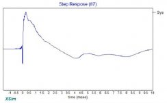
Check out the predicted step response:
https://www.diyaudio.com/community/...ligned-rs225-8-and-rs28f-in-waveguide.360445/
Check out the predicted step response:
Attachments
Thank you! I’ll check it out. One thing I found was that I seem to hear an audible difference between a 1.5khz and the same crossover with additional notches >4khz to push the cone breakup farther down. I think I need to measure that pretty carefully when I go to the analog filter design, and re-prototype with a blind test to see if I hear additional high cuts on the woofer or not. I was kind of thinking of a “cauer-eilliptic” crossover like Mark K and Jon M (on Htguide) have used with Dayton reference woofers before. It looks challenging but effective.
Today I was able to take the prototype speaker out to an aircraft hangar to get some ground plane measurements with a marked turntable, and I’ve attached the results. Unfortunately it looks like there’s an unavoidable loss of directivity control from 1.5-3khz or so, and so I need to find a smaller woofer or larger waveguide to pull this off. I’ll post the woofer and tweeter measurements in a little while.


Nice case study! And hangars come in handy. What causes the loss of directivity? Did you consider changing the baffle width?
I'd suspect the ground plane measurement is the problem. With all that space why not put it on a tall stand? Also any reason for not flush-mounting or edge treatment? I know the temptation with a waveguide and bigger woofer is no edge treatment, but that might be part of the directivity problem.
+1. That's what I'd try (flush mount, baffle round over and gated farfield) before giving up and changing drivers
I often use a 40in tall stand and 0.5m away at 2.0Vrms. SPL is same as 2.83vrms at 1m. Helps reduce effect of floor bounce and other reflections. Floor mounted mic is really for characterizing the bass of subs. All stuff above 100Hz should be away from surfaces such as a tall stand.
Thanks for the replies, all!
First I want to reply to the questions about the choice to do ground plane measurements to higher frequency. It was convenient to do it this way since in order to really take advantage of the space I'm going to want to raise the speaker fairly high. I can do it, but it's going to take some construction to do it safely. I had previously seen some examples of other people doing it, so by angling the mic down I figured that I would have valid data from at least 200hz to ~10khz to tell me what's going on with directivity and if my crossover is working out. Here's a thread with an example: https://www.audiosciencereview.com/forum/index.php?threads/erinsaudiocorner.11219/page-9
It seems like Erin found decent results for a flat hard cement floor with the tilted mic. If I missed something, I apologize for the oversight and would like to hear about it.
Next, why not flush mount? Pure laziness. I apologize for that, and I'm not trying to judge the high end of the waveguide too harshly for that reason. The >10khz dip shows up in the original waveguide on-axis data, so I'm not too worried about that beyond considering trying the fabric dome to see if I prefer its sound. https://www.somasonus.net/dayton-rst28
Someone elsewhere suggested that the 2khz issue could be diffraction, so I set up the diffraction tool in Vituixcad to see what it showed. Here it is with my box using a 6" woofer diameter and sharp corner:
 6inwoof.png")
If I reduce the diameter much, say to three inches, the 2khz widening gets more severe. Could this be what a cone starting to enter breakup would do?
 3inwoof.png")
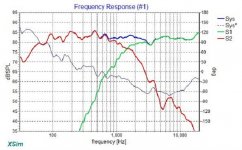
Now here's the raw data of just the actual RS225 woofer that I collected with no crossover or filter:

And finally for completeness, here's the tweeter data:
 tweter.png")

The next thing that I'm definitely going to do is to try repeating these measurements with a 2" radius edge on the box. I'm printing those now, and I plan to hot glue them to the exterior and stuff them full of foam or cloth to keep them dead.

I've heard from enough of you that I should try to get these up off the ground that I'm also going to put in some legwork for that. I'll see if I can get ~10ft high.
First I want to reply to the questions about the choice to do ground plane measurements to higher frequency. It was convenient to do it this way since in order to really take advantage of the space I'm going to want to raise the speaker fairly high. I can do it, but it's going to take some construction to do it safely. I had previously seen some examples of other people doing it, so by angling the mic down I figured that I would have valid data from at least 200hz to ~10khz to tell me what's going on with directivity and if my crossover is working out. Here's a thread with an example: https://www.audiosciencereview.com/forum/index.php?threads/erinsaudiocorner.11219/page-9
It seems like Erin found decent results for a flat hard cement floor with the tilted mic. If I missed something, I apologize for the oversight and would like to hear about it.
Next, why not flush mount? Pure laziness. I apologize for that, and I'm not trying to judge the high end of the waveguide too harshly for that reason. The >10khz dip shows up in the original waveguide on-axis data, so I'm not too worried about that beyond considering trying the fabric dome to see if I prefer its sound. https://www.somasonus.net/dayton-rst28
Someone elsewhere suggested that the 2khz issue could be diffraction, so I set up the diffraction tool in Vituixcad to see what it showed. Here it is with my box using a 6" woofer diameter and sharp corner:
If I reduce the diameter much, say to three inches, the 2khz widening gets more severe. Could this be what a cone starting to enter breakup would do?
Now here's the raw data of just the actual RS225 woofer that I collected with no crossover or filter:
And finally for completeness, here's the tweeter data:
The next thing that I'm definitely going to do is to try repeating these measurements with a 2" radius edge on the box. I'm printing those now, and I plan to hot glue them to the exterior and stuff them full of foam or cloth to keep them dead.
I've heard from enough of you that I should try to get these up off the ground that I'm also going to put in some legwork for that. I'll see if I can get ~10ft high.
Attachments
I think you are right about validity of the ground plane measurement.
I suspected the baffle width guilty of the wide dispersion at 2kHz, combined with the beaming from 700Hz to 1,5kHz. Your simulations seem to point in that direction too. Both your measurements of woofer and tweeter show the same pattern actually. Cone breakup, as far as I understand, the 225 starts that at higher frequencies and not recessing gives issues at higher frequency so these are no causes I think. Could be the combination of the almost similar 'cone' profile of both transducers and the chosen baffle width all sum up to this.
I suspected the baffle width guilty of the wide dispersion at 2kHz, combined with the beaming from 700Hz to 1,5kHz. Your simulations seem to point in that direction too. Both your measurements of woofer and tweeter show the same pattern actually. Cone breakup, as far as I understand, the 225 starts that at higher frequencies and not recessing gives issues at higher frequency so these are no causes I think. Could be the combination of the almost similar 'cone' profile of both transducers and the chosen baffle width all sum up to this.
I'm not sure if this makes it easier or harder to see and interpret, but here's the same data as traces with a 12ms gate, from 0-90 degrees.

Compared to the manufacturer data I'm seeing the on-axis start falling off a bit lower in frequency and a bit steeper.

Maybe "breakup" isn't the right word, but I think what I'm seeing is that it's not behaving as pistonically as I'd like above about 1.4khz.
Compared to the manufacturer data I'm seeing the on-axis start falling off a bit lower in frequency and a bit steeper.
Maybe "breakup" isn't the right word, but I think what I'm seeing is that it's not behaving as pistonically as I'd like above about 1.4khz.
Hint: it's not a piston, at least not one with a flat top, but a cone, about 2" deep. Which explains the drop at 3k on axis.
I hadn’t thought of that part of it, but I guess it makes sense. Regardless, it harms the driver’s usefulness above the ~1.4khz limit that I found. Perhaps with diffraction addressed I can make a better transition.
Today I tried out some 3D printed corner rounds to add a 2” radius to the cabinet. I repeated the plain cabinet measurement to keep it directly comparable- this is with no DSP or EQ, and with a little lepai amp instead of the much larger heavier rig I carried last time.


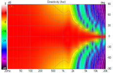
First is the repeat measurement showing the 12x17” box with just the woofer playing.
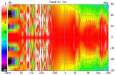
Next is the measurement performed with the rounds taped into place.

I don’t think I see any noteworthy change to the dispersion at 2khz, but it’s wider at 1khz with the radius.
Presented another way, here are the directivity indices:


I didn’t expect miracles, but I was hoping for a bit better than this.
First is the repeat measurement showing the 12x17” box with just the woofer playing.
Next is the measurement performed with the rounds taped into place.
I don’t think I see any noteworthy change to the dispersion at 2khz, but it’s wider at 1khz with the radius.
Presented another way, here are the directivity indices:
I didn’t expect miracles, but I was hoping for a bit better than this.
Flip the tweeter polarity. Something is seriously wrong and I don't think it is the speaker. Is this still ground plane?
.
.

Sorry, I should have been a lot more clear. This is only the completely unfiltered woofer. No tweeter, no crossover. I can repeat tomorrow with the tweeter.
The effect is there, and some of it comes to you in the form of being more direct, not including as much diffraction, which does more than just change the directivity and responses.I don’t think I see any noteworthy change to the dispersion
You nailed it on the diffraction effects and baffle step function of the enclosure, I think. If you want to get rid of this, go for a bigger/smaller baffle, or, put another way, a different ratio between baffle width and cone diameter.
A few here who are experienced in BEM modelling probably could predict things better, but with VituixCAD, Basta! or The Edge you can easily check for yourself your baffle leads to a step around 800Hz and invariably to more beaming from 800Hz upwards. Point is, there always is a diminished region of beaming higher up, and yours might coincide with the polar characteristic of the cone itself. But that is just guessing from what I know.
A few here who are experienced in BEM modelling probably could predict things better, but with VituixCAD, Basta! or The Edge you can easily check for yourself your baffle leads to a step around 800Hz and invariably to more beaming from 800Hz upwards. Point is, there always is a diminished region of beaming higher up, and yours might coincide with the polar characteristic of the cone itself. But that is just guessing from what I know.
- Home
- Loudspeakers
- Multi-Way
- Compact sealed RS225-4 with RST28a and 3D printed waveguide