Does anyone have a PSpice model for common mode choke?
It is not easy to implement it since it hase "two behavoirs": diffrential mode and common mode.
It will be good also to have only the diffrential mode..
Thanks in advance
Eyal
It is not easy to implement it since it hase "two behavoirs": diffrential mode and common mode.
It will be good also to have only the diffrential mode..
Thanks in advance
Eyal
Eyal:
a common mode choke can be modeled simply as 2 mutually coupled inductors each of inductance say L. When they are wired with the correct polarity, the mutual inductance will "cancel out" the total of each self inductance ( M = 2*L), thus for differential currents total apparent inductance = 0, and for common mode currents total apparent inductance = 2 * L.
here is the model in SPICE
.subckt ComModeChoke InA InB OutA OutB
L1 InA OutA .5H
L2 InB OutB .5H
K1 L1 L2 0.99999999
.ends ComModeChoke
To use, connect a source to InA and InB, and a load to OutA and OutB.
I have used .5 henries just as an example to produce 1 H of common mode inductance. You will have get a "real" value from a spec sheet or measurements.
you could add core models to the inductors if you wanted to get fancy but the above model is the basic idea.
Another way to do it would be to run 2 wires through a ferrite bead, which is how many common mode chokes are physically constructed, but I have only ever found SPICE models for ferrite beads with just one wire in them.
Sorry, small math error, .5h on each leg will produce 2H effective common mode inductance, not just 1.
Lt = L1 + l2 +/- 2*M
and M = k* sqrt(L1 * L2)
Lt = L1 + l2 +/- 2*M
and M = k* sqrt(L1 * L2)
For a typical CML you want less than 0.9999999 coupling.
The coupling number sets how much common mode vs. differential mode inductance will result. Most "catalog" CML's have intentionally poor coupling so that they have significant differential mode inductance.
I think a number between 0.80 and 0.90 should suffice for most CML's. If you have a datasheet you can calculate it.
The other option is to model it as four inductors: two coupled with 100% coupling, and two uncoupled. The uncoupled pair are the differential mode inductance, the coupled pair is the common mode.
Pete
Re
Thank you, gentleman.
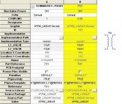
I've faced some difficulties to creat the SPice model with the relvant drawing (Spice part).
I've found the XFRM_LINEAR part (see attachment) which is a transformer build by 2 inductors with coupling factor (=mutual inductance?).
It will work as CMC for defrential mode simulations? How can I test/verify it?
Thank you, gentleman.
I've faced some difficulties to creat the SPice model with the relvant drawing (Spice part).
I've found the XFRM_LINEAR part (see attachment) which is a transformer build by 2 inductors with coupling factor (=mutual inductance?).
It will work as CMC for defrential mode simulations? How can I test/verify it?
Attachments
- Status
- Not open for further replies.