Better late than never (not always!!) The input stage compound is really a common-base/common-collector and provides an easy to predict input impedance. Assuming very high gm's in relationship with physical resistors used, the input current into the common-base transistor develops a voltage I1*R10. (I1, input current, R10, collector resistor, from original circuit post #1). The emitter of Q2 (follower reflects) the same voltage, in turn returned into the base of Q6. The voltage at the emitter of Q6 (input node) is then I1*R10. Then the input resistance to the compound is R10 (the load resistor of Q6). Not an easy task for a single common emitter stage!.Sorry if my post wasn't clear. I compared the original circuit, the common base input stage on its own, and a complementary common emitter stage with bias point and surrounding impedances matched to those in the common base stage. I simulated the full circuit twice, once with the global feedback connected and once with it disconnected.
I ran AC simulations to get small signal input impedance. First, I ran simulations on each circuit with R18 at 10K, which is where I got the first set of numbers. Then I changed R18 to 1G to essentially eliminate it and more clearly expose the inherent input impedance of the circuit, which gave the second set of numbers. For flexibility in simulating multiple situations, it was easier to change R18 to 1G than to simply delete it.
The main point of interest for me is seeing that the common base/common emitter (Blesser Super Transistor) arrangement has a very similar input impedance to a common emitter alone.
One correction to the original numbers: The slight impedance discrepancy between the common base input stage alone and the full circuit without feedback was due to Ian and I using different models for the MJE340. When using identical models, the input impedance for the two circuits become essentially identical.
In the new version of the circuit that I depicted in post #43 there is a resistor divider (x10) between the emitter follower output and the common base device (R7-R5 in holi_gm3).
The result is to present to the input only a fraction (1/10) of the output voltage. The input resistance of the compound is then the collector resistor of the common-base divided by this feedback factor (1/10). Simulation reflects this fact almost perfectly.
An additional advantage of the stage when compared with a common emitter (other than a predictable input resistance) is a very low output impedance. It also provides a well controlled gain of 10. A disadvantage of the compound stage is that you pay the higher bandwidth benefit with a 12dB/octave slope that can be troublesome when the stage is included in an amplifier. I am referring here at a comparison between this stage and the usual common-emitter/common-collector two stage amplifier.
Hi JMFahey,Hola colega 😉 con qué marca los vendían?
Hi partner, interesting, what brand were they sold under?
Never heard of commercial Lateral Mosfet use before (in Argentina that is) because they were always very expensive and hard to get here.
As a side note, the 90´s were HARD for any local manufacturer, 1:1 de facto dollarization plus never stopped inflation meant imported stuff was sold way below our local manufacturing cost .... unfair competition and impossible to sustain.
Many/most excellent product manufacturers bit the dust and had to close.
In 1982 in Argentina, a local audio technician (Agustin Seijas) designed for a Sonolink Argentina an amplifier using the top of the line Hitachi lat. mosfet K176-J56. These amplifiers were used in the pro as well as the audiophile market. The production last until 1995 and well over four thousand were manufactured. Amazing amps. both in SQ and reliability.
However as sheer quantity the bipolar output Audinac AT510 has still the record with over 25K sold units.
Attachments


I do not think getting the schematics will be an easy task.
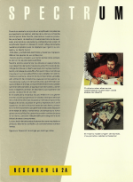
As you can see in the pictures the input stage and VAS were potted and the schematics were not shared.
As far as I recall from 1985 the owner of Sonolink/Sonotechnika (Micky Hapke) told me the amp was designed at his request to fulfill their need of a power amp capable of delivering 200W/8ohms and 400W/4ohms to power their EV speakers.
It was beautifully built and good sounding; but I will disagree with the reliability.🙁
High current in collector input devices is for me a major concern (it was not in 1995!) for a new design. At the point where crossover distortion occurs gain is very low and no amount of. feedback is effective. Feedback only results in an enormous increase in the error signal that ends up on the collector current of the input devices (when overall feedback is used).Are you talking about high current spikes in the output devices only, or somewhere else?
Did you measure the THD of this design? I'd be interested to know how it performed.
Distortion was measured only at 240Watt/8 ohms and it was below 0.1% at any frequency. It was considered a very good result considering the simplicity of the design when compared with most current designs at the time (differential pair at the input).