That was certainly the conclusion I came to. And it seems Phillips MFB speaker engineers came to the same conclusion about three decades earlier!Then given the choice of displacement, velocity, or acceleration feedback, acceleration would be the correct criterion for flat sound output level?
I suspect the transition from entirely stiffness-controlled motion (well below f0) to entirely mass-controlled motion (well above f0) happens over several octaves, so the benefits of MFB are heard and measured even above f0, at least for an octave or two.
-Gnobuddy
That was certainly the conclusion I came to. And it seems Phillips MFB speaker engineers came to the same conclusion about three decades earlier!
I suspect the transition from entirely stiffness-controlled motion (well below f0) to entirely mass-controlled motion (well above f0) happens over several octaves, so the benefits of MFB are heard and measured even above f0, at least for an octave or two.
-Gnobuddy
Absolutely. My recollection is a feedback factor wasn't even required at the fundamental. For low distortion output for a 30 Hz input for example, the feedback at 30 Hz could be near zero. But a good feedback factor was required at the next two harmonic frequencies 60 Hz and 90 Hz. The fundamental could be well below Fr and the third harmonic well above Fr.
Acceleration feedback was the clear winner for me back then even outside of the availability of the Philips drivers. Firstly, it can have a wide useful bandwidth when the sensor is mounted properly. Secondly, the sensor is immune to the electromagnetic coupling and thermal issues of velocity sensing with coil(s). Thirdly, they are inertial and immune to vibration of structures that aren't supposed to be involved with producing sound.
But to me this was the main thing. In a perfect world, you wouldn't need to operate a dynamic HiFi speaker outside of its mass-dependant region for the good reasons Gnobody has stated earlier in this thread. In this region, the amplifier sends an acceleration signal to the speaker, what you measure with the sensor is acceleration and acceleration is directly proportional to SPL. With accurate acceleration sensing and the speaker acting as a rigid piston you don't even need a microphone to know what the frequency response will be.
So I might sum it up this way. With accelerometer feedback we have the best feedback solution for the 'ideal' mass-dependant region but we need to take the steps required for it to work down into the 'necessary evil' compliance-dependant region and to not introduce instability where higher frequency resonances will occur.
![_DSC2594[1].JPG](/community/data/attachments/667/667981-dabf7fd98b2da5141c57a976c416c58a.jpg?hash=2r9_2YstpR)
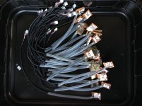
Plug in PCB for the Fusion plate amp with a very low latency dsp in the mfbfeedback chain and current control...
We achieve 30db feedback levels!
Interesting! What are the component Part numbers required to assemble a system? What is the process for tuning the feedback loop?
![_DSC2359[1].jpg](/community/data/attachments/668/668027-1f13f4f18f603afd483a3700cc99841b.jpg?hash=HxP08Y9gOv)
Last edited:
rscamp's post #814 really deserves a close re-reading for the wisdom it contains. But it would have been a bit clearer if it included the words, "... due to the Fletcher-Munson curves, you hear that erroneous 90 Hz harmonic as if it were far far louder than the fundamental..."....The benefit of MFB is something else: it's the ruler-flat frequency response - in the frequency range where it matters - and the crisp transient response that goes with it. The tightest, purest bass I've ever heard came from the MFB system I prototyped....
A minor quibble for Gnobuddy's smart post: it's not so much that the bass FR is "ruler flat" (which in homes sounds really deficient in bass oomph), but that it has the inevitable (but noxious) resonance tamed, thus making the FR curve smooth but not flat.
My intuition is that taming the resonance has a much greater impact on the sound than just cleaning up notes that hit within that narrow band. Wouldn't the resonance be like a drone on a sitar ensemble, introducing a colouration whenever anything in the sub-woofer band is input?
I'd say the improvement in transient "speed" and "tightness" is the most immediately perceptible benefit (including Stomping' Tom Connors, the late Canadian musician). Also, you immediately sense that benefit with the first drum whack while it takes a while to "hear" an FR.
Apropos rscamp's comment in post #822 ("In a perfect world, you wouldn't need to operate a dynamic HiFi speaker outside of its mass-dependant region for the good reasons Gnobody has stated earlier in this thread."), that's a way of saying it is bad design to have a sub-woofer system that has a resonance inside the band the sub-woofer is suppose to play. Beats me why almost nobody makes a driver with a low enough resonance.
B.
Last edited:
The plugin mfb dsp board with ADAU1777:
Does this plug into any Hypex plate amplifier? Is it programmed with Hypex tools or the AD tool SigmaStudio or ??? Do you provide any guidance on its use?
Interesting! What are the component Part numbers required to assemble a system? What is the process for tuning the feedback loop?
This is a project which a do with Rob Munnig Schmidt.
All processing ( also the summing stage) is done in dsp, input signal is straight from a I2S output from the Fusion DSP.
Programming is done in Sigmastudio and to create a loopcurve you will need a testbox where you can measure in open and closed loop.
... it would have been a bit clearer if it included the words, "... due to the Fletcher-Munson curves, you hear that erroneous 90 Hz harmonic as if it were far far louder than the fundamental..."
I couldn't agree more and I think this issue is generally under-appreciated with regard to low frequency reproduction.
Agreed, smooth is good. A smooth frequency response translates to a better transient response when compared to a wiggly or bumpy frequency response....it's not so much that the bass FR is "ruler flat"... but that it has the inevitable (but noxious) resonance tamed, thus making the FR curve smooth but not flat.
The mathematically ideal flat response from DC to daylight produces the correspondingly ideal transient response: A Dirac delta function, i.e. a transient of zero time duration and infinite height.
The much fussed-over Butterworth frequency response isn't particularly wonderful in terms of transient response, particularly when looking at, say, a 4th order filter (such as a woofer in a ported enclosure.)
The merits of accuracy (flat response) versus subjective preference ("house curve") are another discussion altogether. 🙂
But MFB will give you a more accurate woofer, which means you can then more accurately shape it to your desired "house curve", should that be your goal.
Nowadays I do much of my music listening in the car, on the way to and from work. The car is old enough to have a CD player, and I still have hundreds of CDs, so that's what I usually listen to. It's amazing how much difference there can be in overall frequency balance from one CD to the next, presumably due to the mix engineers preferences. EQ'ing one CD to sound better often means the next CD sounds worse.
So it doesn't seem to me that there is one "house curve" (or car curve) that produces the most pleasant results.
-Gnobuddy
...Apropos rscamp's comment in post #822 ("In a perfect world, you wouldn't need to operate a dynamic HiFi speaker outside of its mass-dependant region for the good reasons Gnobody has stated earlier in this thread."), that's a way of saying it is bad design to have a sub-woofer system that has a resonance inside the band the sub-woofer is suppose to play. Beats me why almost nobody makes a driver with a low enough resonance.
B.
Hmmm. Just ran across this:
Strassacker: Speaker Building, Components
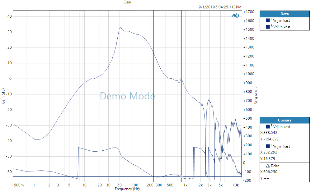
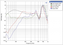
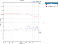
Some measurements from the Fusion MFB controler.
These are done with the SEAS L26RO4Y with a production fault which leads to higher distortion levels.
Open loop gain:
Distortion taken from the sensor (100db spl):
Legenda from top to bottom
Voltage amp no MFB
Current amp no MFB
Voltage amp MFB
Current amp MFB

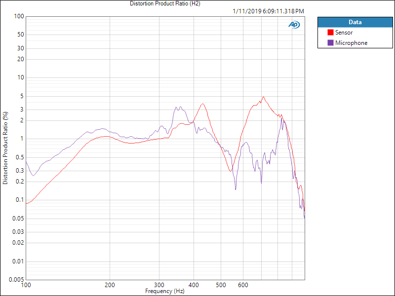
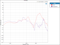
Total THD sensor / mic at 100db spl:

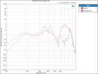
2th harmonic
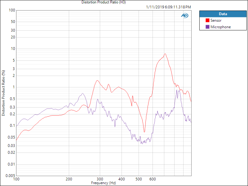
3th harmonic
Mic measurements were done above 100Hz only because the small room.
These are done with the SEAS L26RO4Y with a production fault which leads to higher distortion levels.
Open loop gain:
Distortion taken from the sensor (100db spl):
Legenda from top to bottom
Voltage amp no MFB
Current amp no MFB
Voltage amp MFB
Current amp MFB
Total THD sensor / mic at 100db spl:
2th harmonic
3th harmonic
Mic measurements were done above 100Hz only because the small room.
Attachments
-
 Open%20loop%20FRF%20L26RO4Y.png59.3 KB · Views: 753
 -
 Tot%20HD%20stroom-spanning-L26RO4Y%20MFB%20en%20non%20MFB%2096dB.PNG94.4 KB · Views: 730
 -
 THD%20Ratio%20microfoon%2098%20dB%20near%20field.png37.2 KB · Views: 718
 -
 2nd%20HD%20Ratio%20microfoon%2098%20dB%20near%20field.png34.1 KB · Views: 721
 -
 3rd%20HD%20Ratio%20microfoon%2098%20dB%20near%20field.png35.4 KB · Views: 702
...https://www.lautsprechershop.de/hifi/ripol_en.htm]Strassacker: Speaker Building, Components[/url]
Thanks for link to slot-loaded ripole (which also has a funky resonance cancelling tuned circuit using giant capacitors and coils and high output impedance amp). Klipsch and other big horns also use slot-loading for the same purpose, but easier "to get away with it" in a true horn.
Wow, this thread is sure getting hot, as is the fabulous data in rscamp's other MFB thread.
B.
...Wow, this thread is sure getting hot....
As it should! 🙂
I like to say, "Feedback is our future". This goes well beyond MFB speakers. Humans use a huge amount of various types of feedback - i.e. regulating cardiovascular systems, walking, picking up a spoon, nursing an injury, etc., etc. - you name it, we use feedback to do it. The machines (and speakers!) we build will need to use a lot more feedback systems to make them more capable. And in many cases it is cheaper than trying to build in "open loop" accuracy and precision.
Last edited:
Some measurements from the Fusion MFB controler...
Very interesting, Hans! Thanks for sharing.
There is pretty good agreement between the measurements using the accelerometer and the microphone at lower frequencies as I would expect.
Is the problem with the driver the reason you didn't measure HD to lower frequencies?
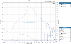
Ok, now for the promised levity…measurements of the Sony SA-W2500 “subwoofer”
Attachment #1: Here is measurements of port, piston, & summation made straight from the test computer, no EQ, no MFB, just woofer + box response. The port response looks more like what I’d expect to see from a 4th order bandpass design. I re-measured it 3 times thinking it must be wrong. Has anybody else seen anything like this before?
Attachment #2: I measured T/S parameters and modeled the response which, surprise surprise, matches the measurements. Yes, you are reading that correctly Sony is using a woofer with a Qts=1.2 in a ported box. Thank goodness for EQ 😉
Attachment #3: Here is a comparison of response as implemented with EQ, LP filter turned to its highest setting, and with/without MFB. You can see that the MFB loop gain is so low (~3dB) it might as well not even be there.
So, let's say i want to improve this subwoofer to lower the frequency, i want it to be deeper and lower.
What adjustments i can to the box ?
My first thought was to change the driver, but i think altering the box or creating another one from scratch is the way to go.
So, in what box will this driver + amp go down ... down ... ?
Looking at the parameters of the woofer (particularly Fs=38 and Qt=1.2), there isn’t much to be done to improve the LF response thru enclosure design. You could double the enclosure size and tune port a little lower at 35Hz and pick up some improvement below 50Hz, but not a lot. Note also that the EQ built in to the amplifier includes a 2nd order HP filter at about 40Hz, so you are fighting against that as well. If sticking with this woofer, the best path to improved LF response is probably added EQ to fix the response to your liking.
Say I use a current amp.Consider the two regions the LF (Low Frequency) speaker needs to operate in. Unlike the midrange and tweeter we want the LF driver to function through its natural frequency. It is helpful to consider these regions the "mass dependent region" above Fr where F=ma rules and the "compliance dependant region" below Fr where F=kx rules.
First, with regard to amplitude, as Gnobody has so clearly pointed out, at low frequencies (the compliance dependant region) the displacement is proportional to the force exerted by the voice coil (F=kx). Displacement will eventually be a constant regardless of frequency as the frequency is lowered. We are conveniently ignoring the error in the air spring contribution to the constant k at very low frequencies due to leakage but that's okay - we are just trying to visualize what us going on. 🙂
How does this change the response? Well, above resonance, the amplitude has been increasing as frequency drops to keep the SPL constant. Below resonance, this isn't happening so the SPL is falling off. In mathematical terms, the RMS pressure is proportional to the square of the frequency and if you do the math this reveals the characteristic 12dB/Oct decay where displacement is a constant. You don't need to know the math, just that the reason for the decaying response can now be easily visualized due to the constant displacement characteristic.
As i understand the cone accelleration is constant vs frequency
Force factor is Newton/Ampere is constant for a woofer.
So if F = ma, a is proportional to current from amp and the same over all frequencies from Fbox and up?
So at Fbox the real part of Z is large. Will voltage at Fbox be huge compared to voltage at Fzmin a little higher up in frequency?
My concern is the voltage swing capability of the current amp. Is it a limit or does it not apply as it is a current amp?
Example 30 ohm at F box and Fzmin = 3 ohm at 90 Hz. Do you need 10 times the voltage swing at F box compared til Fzmin? (V = I*|Z|)
- Home
- Loudspeakers
- Subwoofers
- Commercial motional feedback woofer available sort of