Hi,
What is that circuit you have between the power inlet and the transformer?
It´s a line conditioner.
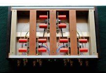
Pulled the boards again and removed all the components except the chips. Re-mounted everything back on the boards using 63/37 solder. The bypass resistors are now mounted directly on the chips. The end result of this is that the amp is now working normally.
The offset drops with source connected to -32mv on the left and -42mv on the right. This looks to be OK but I would feel more confident if someone could confirm this.
The amp sounds very good with my high efficiency speakers. Now all I need is a passive preamp.
Instead of trying to figure out what's poster above saying, please check this link first: http://www.diyaudio.com/forums/audi...-kit-building-instructions-3.html#post1516522
The data sheet for the chip recommends 220pF, but 300 should be fine also. The cap should be as close to the chip's pins as possible. You can either solder it on the backside of the board, or use the same PCB holes as the chip's pins. The leads for a 220pF cap should be very thin so they should fit in there.
Also, power supply decoupling is a must, according to National's datasheet. Unfortunately, there's no provision on the board for this either, so the small 0.1uF caps have to be tack soldered on the back of the board or something like that has to be done.
Ideally, there should be an RFI filter on the outputs as well.
The slew rate for the chip is between 5 and 11V/uS, so this isn't a super fast amplifier.
Hi Peter,
The premium kit supplied a 220R for R1, as according to your user guide that you just placed a piece of wire in its place and alternatively a small e-cap 4.7uf or bigger can be installed there for DC protection. How would these 3 options affect the input and sound for choosing between a wire, a 220R and a small e-cap?
Thanks
Small cap would be recommended if the source outputs DC.
In some cases resistor is useful to eliminate interferences. In most cases it's not needed.
The sound is best without resistor, the worst with cap in place.
In some cases resistor is useful to eliminate interferences. In most cases it's not needed.
The sound is best without resistor, the worst with cap in place.
Hi Peter;
I have rescued some Blackgate caps from a previous build that I no longer use; they are 10uf 50V N's and 2200uf 35V FK's. Would these be ok to use with the LM4780 kit I've ordered and how close to the FK's voltage is it safe to go. Thanks.
I have rescued some Blackgate caps from a previous build that I no longer use; they are 10uf 50V N's and 2200uf 35V FK's. Would these be ok to use with the LM4780 kit I've ordered and how close to the FK's voltage is it safe to go. Thanks.
I'd place FKs on amp board and 10uF caps on rectifier board (negative rail only)
With 2 x 22V transformer you'll be getting approx 32V on rails which is fine with 35V caps rating.
With 2 x 22V transformer you'll be getting approx 32V on rails which is fine with 35V caps rating.
From where can I get the couplers as used in Peters integrated amp for connecting the pot and input switch to the extension rods for the knobs. Thanks.
I source all those parts from a local hardware store: 1/4" brass rod, 1/4" ID water pipe and 1/4" nylon washers.
So its a plastic pipe that's a push fit on the switches and rod. A simple and elegant solution. Thanks Peter.
The pipes I'm getting locally fit nicely over the rods. Initially they were also pretty tight over the pot and selector shafts, but the recently available pipes show slightly bigger diameter. I use copper tape (over the shafts) to improve the fit.
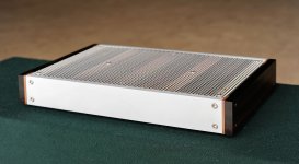
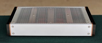

Wow, Peter. Your chassis are just works of art. I just finished my amp, which is on a cutting board until I can get a proper chassis built. Looks like absolute hell, but it sure sounds sweet! I'm torn between just speccing out a chassis from Par-Metal, or building my own. Of course that will mean buying a mitre saw, drill press, etc.
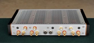
It's hard to believe you're getting holes that clean on the back of your chassis with just the Bosch hand drill. I can't drill that clean with a hand drill to save my life - even with the DeWalt Pilot Points.
It's hard to believe you're getting holes that clean on the back of your chassis with just the Bosch hand drill. I can't drill that clean with a hand drill to save my life - even with the DeWalt Pilot Points.
It's not possible to build chassis like that with a hand drill, I'm using regular drill press for all the drilling.
My amp is built from Peter's LM3875 Premium kit and I'm a little surprised at how good it sounds. The associated equipment is a Wavelength Brick V3 DAC, an Elekit TU-882 preamp I built a few months ago, and a pair of Zu Omen speakers.
I've had a lot of different amps connected to the Omens, mostly SETs and SEPs, but also a few solid state amps, including an old Adcom GFA-5500 and a Bel Canto C5i, which is a Class D amp. I have to say that the gainclone is quite remarkable in this company. It exhibits very authoritative bass in particular, and also a very lively sound. I would say the Bel Canto is as lively and detailed, but lacking in bass authority compared to the gainclone. I wonder if this seemingly powerful bass could have something to do with the rather large transformer I'm using (Antek 400VA).
Also, the Omens are extremely efficient, so the amp runs very cool compared to my initial tests with the small Magneplanars. The amp also sounded very good with the ribbon speakers, but I was always conscious of not pushing it too hard because it would become very hot.
More than my other amps, the gainclone seems to benefit from good power conditioning. Could that have something to do with the sheer simplicity of the circuit? The difference between powering the amp from a standard surge protector and from a mid-range Furman is obviously audible.
Last edited:
I've made a start. First checks were good with just the power supply connected I was getting +35.3vdc and -35.6vdc. With one pcb hooked up to the p/s and ouput with the input wires not yet connected to the LDR volume control and the second board also wired the same but without the plus and minus supply wires connected the light bulb tester glows brightly. Any pointers would be much appreciated. Thanks.
- Home
- More Vendors...
- Audio Sector
- Commercial Gainclone kit- building instructions