Lohengrimas
Please post a picture of how you are measuring. WE could certainly help you after that.
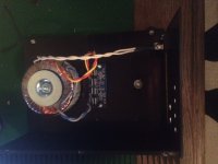
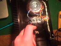
Sorry, creepy hand pics will have to do. I connected everything as per page 26 in the manual, and measuring as pointed out a few pages below that with the con lead on the PG side and the red one on the V (- or +). Thanks in advance.
Attachments
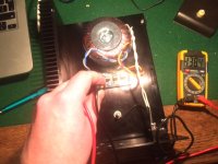
Can you measure AC voltage on transformer's secondaries?
I'm beginning to doubt my sanity here - AC 1 and AC 2 both give a figure of around 154-155-ish. I don't think that's supposed to happen...
Seems either the transformer is defective or the DVOM is...I'm beginning to doubt my sanity here - AC 1 and AC 2 both give a figure of around 154-155-ish. I don't think that's supposed to happen...
Sent from my Nexus 4 using Tapatalk
I'm beginning to doubt my sanity here - AC 1 and AC 2 both give a figure of around 154-155-ish. I don't think that's supposed to happen...
I've had that problem a while ago with another project.
It seems that i had both the secondaries crosswired and that gave some very strange readings.....
Take a new ac measurement between the two secondaries, perhaps they made a mistake with colourcoding the secondaries.
Well, check AC on the mains, this way we can figure out if it's meter or the transformer.
I can't even get a reading of the mains, the meter just comes up blank, even though I can get readings of AC1 AC2 and V-PG.
I tested the meter on some standard duracell AA's, reading 2.00 V.
I'd feel really stupid if it's just a dinky meter.
the battery should be a DC voltage reading. You set the voltmeter to 20.00Vdc and you get a reading of 1.5Vdc.
Lead acid batteries are ~2Vdc per cell.
For a transformer and for mains the voltmeter has to be set to 600Vac.
Lead acid batteries are ~2Vdc per cell.
For a transformer and for mains the voltmeter has to be set to 600Vac.
the battery should be a DC voltage reading. You set the voltmeter to 20.00Vdc and you get a reading of 1.5Vdc.
Lead acid batteries are ~2Vdc per cell.
For a transformer and for mains the voltmeter has to be set to 600Vac.
My meter only runs up to 300Vac.
Still stumped why my readings are so high on the secondaries.
If your DMM is only suitable for less than 300Vac, then check your probes.
They should have a safety rating on them.
All the DMM I have bought in the last 5years have a 600Vac rating to CAT III
They came with probes that have a dual rating: Cat III to 1000V and Cat IV to 600V
The only probes that don't have a safety rating on them came with the DMM I bought ~ 1986, but it shows a 750Vac max for the AC voltage.
Use an attenuated output for the headphones.
A 100r:1r will cut the volume by 40dB and not blow up your headphones if you had left the vol pot at max. This gives the headphones a source impedance of ~1ohm. If you phones need a higher source impedance, you can increase the resistor values
How does one implement such a resistor? In parallel between the 2 channels at the headphone jack?
attach the two resistors in series. That gives you 101r
Attach the 100r to the Hot/Flow output.
Attach the 1r to the Cold/Return output.
The headphone Hot/Flow output comes from the junction of the 100r & 1r
The headphone Cold/Return output comes from the amplifier Cold/Return.
This way the headphones see a source impedance of a tiny bit less than 1r
and the amplifier sees a load a bit higher than 100r
If the 100W amplifier were turned up to just reach clipping the 100r will dissipate less than P=28.2V²/100r = 8W
Use at least 16W of resistor for this arrangement to get 40dB of attenuation from a 100W amplifier.
Use your own values to determine your attenuation and impedances and dissipations.
1875 or 3875?
Hi Peter,
As you had the chance to listen to lm1875 and lm3875 in the same configuration and setup, could you tell me the main differences in sound between them? the output power is not a big issue, since my speakers are 96 dB efficient. Sorry for my poor English. Thanks in advance! 🙂
While the projects described so far were using printed boards, I would like to present now an elegant way to build an amp circuit without PCBs, using point to point wiring technique.
It so happens that I recently received an order for LM1875 amp, which I never tried before, so there was not other way as going p2p.
The amp circuit as presented in National's datasheet:
Hi Peter,
As you had the chance to listen to lm1875 and lm3875 in the same configuration and setup, could you tell me the main differences in sound between them? the output power is not a big issue, since my speakers are 96 dB efficient. Sorry for my poor English. Thanks in advance! 🙂
The important aspect about sharing a single transformer and common rectifiers per two amp channels is power star ground.
While you could simply run PG+ and PG- (ground) wires from rectifier board to each amp board, in some setups hum problems were reported and presently I always use star (power) ground in all my amps.
I simply achieve it by connecting output grounds (OG, on the opposite side of speaker wire connection) with a 14ga solid core copper wire.
The center of that wire is my power star ground and both PG+ and PG- grounds from rectifier board connect here. In the picture below the connections are so short that I used single runs of wire, normally I use two wires for both PG+ and PG-.
Please note that power ground is also directly connected to the chassis.
I specifically refer to it as power star ground, as signal wires from RCAs are not connect directly here. They connect through separate traces on PCB to OG (output ground) pads.
Should the center tap of transformer secondary also connect here ?
The centre tap is part of the capacitor charging circuit.
The centre tap must go to the smoothing capacitors.
No where else.
And keep the loop areas very small. That means use a twisted triplet from transformer to rectifier and from rectifier to smoothing capacitors and from smoothing capacitors to amplifier.
The centre tap must go to the smoothing capacitors.
No where else.
And keep the loop areas very small. That means use a twisted triplet from transformer to rectifier and from rectifier to smoothing capacitors and from smoothing capacitors to amplifier.
Should the center tap of transformer secondary also connect here ?
If you are using my rectifier boards, which are part of the amp kit discussed here, then center tap of transformer secondary does not connect there (wire bridge between OG pads on amp boards).
My rectifier boards are actually designed to work with dual secondaries transformers, not center tapped units, however, there is a mod for that, when center tap transformer can also be used: http://www.diyaudio.com/forums/chip...oid-wiring-peter-daniels-kit.html#post1196283
In either case, secondary wires from transofrmer connect to rectifier boards and not to the wire bridge on amp boards.
Hi Peter,
As you had the chance to listen to lm1875 and lm3875 in the same configuration and setup, could you tell me the main differences in sound between them? the output power is not a big issue, since my speakers are 96 dB efficient. Sorry for my poor English. Thanks in advance! 🙂
I didn't really have much chance to listen extensively to this amp as I rushed to sent it to the customer who requested that chip configuration.
To me, it's a bit too low in power and as such not practical. People say LM1875 sounds even smoother, but I can't really confirm it.
The centre tap is part of the capacitor charging circuit.
The centre tap must go to the smoothing capacitors.
No where else.
And keep the loop areas very small. That means use a twisted triplet from transformer to rectifier and from rectifier to smoothing capacitors and from smoothing capacitors to amplifier.
If you are using my rectifier boards, which are part of the amp kit discussed here, then center tap of transformer secondary does not connect there (wire bridge between OG pads on amp boards).
My rectifier boards are actually designed to work with dual secondaries transformers, not center tapped units, however, there is a mod for that, when center tap transformer can also be used: http://www.diyaudio.com/forums/chip...oid-wiring-peter-daniels-kit.html#post1196283
In either case, secondary wires from transofrmer connect to rectifier boards and not to the wire bridge on amp boards.


Is this is how all the wiring should be done ?
Please excuse shoddy MS Paint job 😉
Last edited:
despite quoting the text of my advice you are again asking for my opinion, so I'll repeat my opinion
Is that an audio sector PCB?
It states "technofreek.com"
I think you are in the wrong section.
AND keep the loop areas small. That means no single wires trailing randomly across the enclosure.use a twisted triplet from transformer to rectifier and from rectifier to smoothing capacitors and from smoothing capacitors to amplifier.
Is that an audio sector PCB?
It states "technofreek.com"
I think you are in the wrong section.
Last edited:
- Home
- More Vendors...
- Audio Sector
- Commercial Gainclone kit- building instructions