Antonio,
That's seems a good deal.
So the selling is saying that this is a 120VA
transformer? OK...that makes more sense.
It's too bad there aren't current ratings on the
secondaries. What is the weight of the
transformer and what are the physical dimension?
It looks like the 18-0-18 secondary is the
'main' one since the wires looks to be the
thickest. Assuming the current capacity is
reasonable, this should work fine.
If you look at the "Dual Complementary Rectifier"
section here
http://www.powertronix.com/html/body_linear.html
you can see a basic schematics on how to use create
the +/- voltage you need.
Cheers,
Dennis
Dennis Hui said:Antonio,
That's seems a good deal.
So the selling is saying that this is a 120VA
transformer? OK...that makes more sense.
It's too bad there aren't current ratings on the
secondaries. What is the weight of the
transformer and what are the physical dimension?
It looks like the 18-0-18 secondary is the
'main' one since the wires looks to be the
thickest. Assuming the current capacity is
reasonable, this should work fine.
If you look at the "Dual Complementary Rectifier"
section here
http://www.powertronix.com/html/body_linear.html
you can see a basic schematics on how to use create
the +/- voltage you need.
Cheers,
Dennis
Basic Math tells us that 120VA assuming line voltage is 120VAC is a 1 Amp primary. So we divide 120 by 36 (18-0-18) Secondaries, and we get 3.3 Amps in series or 6.6 amps in Parallel.
Regards
Anthony
MJL21193 said:I won't stay in this thread, and my knowledge is limited anyway. I am not an expert in this, just another grunt building stuff. Besides, with Dan at the helm, you guys are set.
Thanks for the compliment!! I wish you would stay involved in this thread.
Its ever so much more helpful for me to speak with someone with a different viewpoint, because that's double the resources. . . rather than not increasing the resources with someone who always agrees.
Thanks also for catching my decimal slide math error earlier.
I'd like to ask the favor, if you could check over this post:
http://www.diyaudio.com/forums/showthread.php?postid=1496729#post1496729
of transformer selection, and see if there's any errors.
It seems that I didn't make the point of getting safety by simplicity (avoid the tangle), although I really did put in the effort--so, is there, perhaps, a more thorough way to say it?
Next, I even tried Stancor VS. Spagetti, because one hooks up in under a minute, and the other is better with sauce. 😀
Today, I have been working on Peter Daniel's diagram, and I can report that the schematic is optimal. For general compatibility, we need an input filter cap added. The caveat: In adding an input filter cap instead of that in-series resistance, the DC offset goes way up (the 50k pot becomes isolated by the cap and is no longer able to "add" to the load).
Earlier I had guessed that standard resistor values of 15k or 18k will restore the reference. After some study (the hard way), I believe that the input load value should be 15k. Some confirmation would be much appreciated.
It would be my opinion that for an absolute beginners simple and safe amp you should consider using a wallwart transformer or laptop power supply. It takes most of the danger out of a newbie build and it takes many complications out of the equation. My first project gave me enough trouble without having to worry about lots of volts. See my first build here http://www.diyaudio.com/forums/showthread.php?s=&threadid=119131
The whole thing should cost less than $50 to make buying all new parts and is fairly simple.
The whole thing should cost less than $50 to make buying all new parts and is fairly simple.
Today, I have been working on Peter Daniel's diagram, and I can report that the schematic is optimal.
Peter, I always knew that you would get the hang of it eventually! 😀
Hi Colin -
Regards post # 100 - Please don't take this wrong.
I don't see the thread as wandering at all with exception that some posters are missing the point - that being that some newbees have found 'Kits' simply not designed for them.
I spent a good part of the night going over 4 manufacturers Kits again. It was the 3rd time for 1 of them and the 5th for another. Read and re-read including their manuals for 2 of them that provide anything near worthy of being called a manual.
Once again I was happy I'd not purchased one a year ago. If the answers aren't in the manual, I can't call you on the phone and you don't even answer your mail why would I want to give you my money?
As much as those who have built many of these are confused that 'newbees' don't get it , I am confused that experienced builders can't understand why.
It would take me a couple hours to speak it and several to write what I've found wrong in the best of the manuals. A couple of these are near to excellent and yet I stop and ask why the Author didn't think to address this or that issue here and there or failed to put a photograph at a critical point and the ever present 'Demon' schematic when a drawing of the circuit combined with the schematic would make the thought easy for a newbee to follow rather than have him or her attempt to figure out why the rectangular piece in their hand is shown as a triangle on a schematic and a round multi colored piece of plastic with wires coming from each end is shown as a jagged road . I know adults that can't put together their kids Christmas toys, this is no different in principal.
I look at many of these as completed projects and say - 'piece of cake'. When I read the manuals I say ' What the .... '.
I said from the onset I saw little profit margin for the Kit Suppliers and maybe that's why they don't bother with e-mails but they simply don't or, my guess, can't, think like newbees. Some sell several amps and don't even tell you how many watts per channel the amp provides. They simply assumed the buyer must know the difference between an 1875 and a 3886. Why does 1 Kit provider sell a 3875 with 21 solderable components and another the same chip with 12 solderable components? Answer is obviously the difference in circuitry but what does that mean to any end user beyond the newbee and why can't they take the time to explain such in laymans terms? Part of me believes that because the profit margin is so low they really don't want newbee business - too many 'dumb' questions.
Thats the purpose of this thread. The manufacturers of Kits could learn how to get newbee business if they wanted it by re-learning how many, many people think. Until they do that, we need a new design with easily understood instructions and photos. Once it's assembled, even newbees can say ' Now I see'.
Bluto
DJ Oatmeal -
Not a bad suggestion if it fits with whats being proposed.
Not getting toasted is always a good thing. I had planned on building mine using a tire iron hooked up to jumper cables on my truck battery for soldering while drinking Gin and Tonic in my pool and was a bit concerned over this.
Some guys claim 75 cents a watt complete. Nice goal.
Bluto
Hey Greg !
Thought I'd seen every Amp that existed.
This one is cool. Too bad it's low powered. Would make outstanding computer speaker amp.
I followed the links a bit and they are just great as well. These people were thinking. I'm going to investigate site further.
Thanks - Bluto
Thought I'd seen every Amp that existed.
This one is cool. Too bad it's low powered. Would make outstanding computer speaker amp.
I followed the links a bit and they are just great as well. These people were thinking. I'm going to investigate site further.
Thanks - Bluto
Bluto said:Hey Greg !
Thought I'd seen every Amp that existed.
This one is cool. Too bad it's low powered. Would make outstanding computer speaker amp.
I followed the links a bit and they are just great as well. These people were thinking. I'm going to investigate site further.
Thanks - Bluto
get a full ranger driver with spl >= 90dB, and you are in business, eg fostex 167E or 127E. this combo will sound good, possibly remove a few components from amp., eg coupling cap, high pass components, bypass caps, etc
danielwritesbac said:For general compatibility, we need an input filter cap added. The caveat: In adding an input filter cap instead of that in-series resistance, the DC offset goes way up (the 50k pot becomes isolated by the cap and is no longer able to "add" to the load).
Earlier I had guessed that standard resistor values of 15k or 18k will restore the reference. After some study (the hard way), I believe that the input load value should be 15k. Some confirmation would be much appreciated.
Yes, 15k combined input impedance (with 22k feedback resistor) is about right for reasonable offset levels.
I had a Gaincard for testing and they use coupling caps at the input. The offset was always 85mV (attenuator before the cap).
I compiled some useful links with regards to chipamps, that some of you may find interesting:
GC ground arrangement:
http://www.diyaudio.com/forums/showthread.php?postid=787773#post787773
300pf cap:
http://www.diyaudio.com/forums/showthread.php?s=&threadid=55300&highlight=
Wiring CT transformer:
http://www.diyaudio.com/forums/showthread.php?postid=548382#post548382
Wiring LM3875 kit:
http://www.diyaudio.com/forums/showthread.php?postid=1108820#post1108820
Modyfying dual bridges into single bridges:
http://www.diyaudio.com/forums/showthread.php?postid=1196283#post1196283
GC clipping:
http://www.diyaudio.com/forums/showthread.php?postid=1262953#post1262953
GC upgrades:
http://www.diyaudio.com/forums/showthread.php?postid=1231532#post1231532
LM3875 as a headphone amp:
http://www.diyaudio.com/forums/showthread.php?s=&threadid=62828&highlight=
Capacitors evaluation:
http://www.diyaudio.com/forums/showthread.php?postid=574431#post574431
http://www.diyaudio.com/forums/showthread.php?postid=581230#post581230
LM4780 / 3886 / 3875 / 1875 Comparison
http://home.pacific.net.au/~gnb/audio/lmcomp.html
My two sense.
I see two main thrusts here:
1. The original goal, of purchasing an entire kit with all parts as well as product support. I think Peter has already mentioned that he is willing to do this. I've built two of Peter's kits. I prefer to have everything neatly laid out on a circuit board. He provides excellent product and service.
2. The people who want to redesign the wheel from the axel. In this case, read Nuuk's site. If this isn't enough, I would suggest that you try to find someone in your area to mentor you. The internet is good for a lot of things, but I wouldn't risk my life doing anything I read here.
Please, do not underestimate working with mains voltages.
If you have questions about what a component is/does, look it up. Wikipedia is a good place to start. Your local library is another... I bet there are 15 good books on basic circuits / electronics for the beginner that you can read for free.
Dennis Hui said:Antonio,
......
What is the weight of the
transformer and what are the physical dimension?
It looks like the 18-0-18 secondary is the
'main' one since the wires looks to be the
thickest. Assuming the current capacity is
reasonable, this should work fine.
If you look at the "Dual Complementary Rectifier"
section here
http://www.powertronix.com/html/body_linear.html
you can see a basic schematics on how to use create
the +/- voltage you need.
Cheers,
Dennis
Dennis,
The transformers are about 9.5 cm diameter by 4 cm. Not very heavy , maybe 750grms.
I read your link about Dual Complementary Rectifiers. How can I calculate the resistors and caps values?
In fact my idea was to build a very simple rectifier, like the one shown in the link below, where there are no capacitors or resistors, only the MUR860s. Do you think I could do this with my toroids:
http://dogbreath.de/Chipamps/GainCardCopy/GainCardCopy.html
Actually I am copying also the amp's configuration in that same page (which is supposed to be a replica of the original gaincard and the gaincar's psu ).
Regards
Antonio
It is shocking to see the denial in which we sometimes persue our hobby... I did some costings in the week to do an LM1875 kit, and looked at the full package... very easy to hit $100 just in component cost, useing no boutique parts.... well transformers are nice potted torroids... and a beefy heatsink.
Normally this cost totaly escapes us when we build up units piecemeal...
Normally this cost totaly escapes us when we build up units piecemeal...
I do have a few comments. This is in regards to the original poster's famous speaker in combination with this amplifier project.
1
The "schoolies" amplifier is a LM1875. The Pioneer B20 has a whizzer cone. This combo will go loud enough to rattle the whizzer--at which point any volume is excessive.
Note: The problem between LM1875 and beginners is just one thing--use a mica pad between it and the heatsink or you get a shock.
2
To scale up, the very next step is to adapt over to the style of "Harbeth Monitor 40" so that the B20 becomes a wideband driver and then an Efficient prosound woofer is added. In addition, one may want to consider Pioneer's little silk dome, which is a good match for the B20. The hifi-prosound fusion doesn't sink the B20's pretty midrange, but rather raises everything else up to match.
Scaled up like that, the LM3875TF looks like a great option for powering it. It is also good because its safely insulated.
Peter Daniel said:Yes, 15k combined input impedance (with 22k feedback resistor) is about right for reasonable offset levels.
I had a Gaincard for testing and they use coupling caps at the input. The offset was always 85mV (attenuator before the cap).
Peter, you're awesome.
So far, I've had good luck testing out several different gainclones with 15k input impedance, 4.7uf, plus an Alpa A20k potentiometer.
I've also had good luck with Page 16 of LM3875.pdf and the little claim about gain providing more power and headroom. . . up to a limited extent.
In my opinion, that's gain 35, because. . .
The NFB of 820R and 27k was a lucky combination. This I tested with the pot wide open, and the following trouble sources:
A PC sound source.
A digital television (variable output jack).
An MP3 player (several RCA, including Pearl).
It was helpful to some extent. Particurlarly surprising was the RCA Pearl source that had a "dirt to diamond" transformation when it was allowed a normal level output rather than being pushed.
You know what I'm thinking. . . Beginner's amplifier and Beginner's source devices, together in system symmetry.
EDIT: This circuit works on LM1875 too--no more nfb cap. 😀
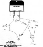
Howabout this for LM3875TF:
Attachments
Wow - Thread keeps getting better !
TTan 98 -
I've got a few possibilities for front end but I want to keep my CSS FR125's just because I like them. Pretty inefficient. I'm playing with a FR Line array of Micsos that give me an spl of over 103db. I like them but something is missing. I'm working on it . That amp would do the trick with them.
shallbehealed -
I'm trying to get an Audio club started in my area. Very rural. I'd love to have a mentor.
I know I make jokes regards the electricity but I do take it very seriously. I'll be doing a good deal more reading before starting. Again - sorry, show me the kit manual that has an entire chapter dedicated to your safety in building their amps. Show me the kit manual that even has periodic warnings within it's instructions at points of build that your failure to do as instructed could result in serious injury or death. If I'd see that instruction throughout Kits manuals I'd have more respect for them. If they are not in the Kits manuals, why would you want to send a newbee in that direction? I'll near to bet the most you'll find is a standard 'legalize' warning which is nothing but a disclaimer to protect them from liability.
If you follow the thread from the beginning you'll see Gychang (threads Author) decided on a scratch build from near to the beginning and that based primarily on his personal experience. It's been others that keep bringing up kits despite that. I've said enough on that subject, I only comment because a few have stated the thread was about 'either or' .... the thread is not . It was a question that became a decision in about 6 posts. I may yet build a kit myself if objections I've stated are overcome. Gychang asked me just this AM what I thought of a particular Kit he'd seen so apparently he hasn't ruled them out altogether either. I don't know why those who haven't read the entire thread don't start a new thread entitled " Why you should build a Kit rather than a scratch build Amp'. Seems many people object to the idea despite the Gallery being full of them. I don't understand that. Much of the Gallery is clones of someones 'scratch build' design. Why the continued objection to a new one?
Dan -
Good info on possible use of Pioneer B20. I just saw something mentioned that was similiar elsewhere. Possibilities here. Some drivers just keep coming up.
Bluto
The NFB of 820R and 27k was a lucky combination. This I tested with the pot wide open, and the following trouble sources:
Particurlarly surprising was the RCA Pearl source that had a "dirt to diamond" transformation when it was allowed a normal level output rather than being pushed.
The "schoolies" amplifier is a LM1875. The Pioneer B20 has a whizzer cone. This combo will go loud enough to rattle the whizzer--at which point any volume is excessive.
Note: The problem between LM1875 and beginners is just one thing--use a mica pad between it and the heatsink or you get a shock.
The 1m load at the amp board acts as a slight divider upon the input cable that leads to the pot.
EDIT: Here's a frequent example of a visual complexity: The chipamp.com power supply has a simple and elegant schematic. . . however, the beginner is often thoroughly confused during its assembly and hookup.
I think we got a solution. It was "Plan A" anyway.
That's a "factory standard" chip amp implemention with component values from LM3875.pdf.
Given the resources of a 50w amplifier, I'd estimate the dc offset tolerance figure at 70mv. EDIT: That's a guess because my old meter can only read amperage at such low figures.
We could skip that too, if we could pump up the LM3875TF's gain up to about 38 (barely sufficient), and also have a dc coupled (no cap) NFB, and also have very low dc offset, as not explained on page 16 of LM3875.pdf.
So, how do we do it?
With the modern "ear protection" variable outputs, the output power is lacking on these devices. They are often able to output "tones" at their stated power; however, there is much distortion of mp3 format music whenever headroom is zero.
Here is my "Ladderback" power supply. You may use it for non-commerial, diy projects.
For academic reference, its centerline tolerance is approximately 30vdc.
As for this thread, I have reported post#68 (my own post) to the moderator and asked for its removal on the grounds that its confusing. . .
I was thinking of a web-based assembly manual, mostly photos, with very little chatter.
Just so I have got this quite clear - is the above from one half of the team who is going to provide a crystal clear GC building guide for complete beginners?

Nuuk said:Just so I have got this quite clear - is the above from one half of the team who is going to provide a crystal clear GC building guide for complete beginners?
Of course!! Its the other half that's crystal clear. 😀
- Status
- Not open for further replies.
- Home
- Amplifiers
- Chip Amps
- Commercial complete Gainclone kit for a beginner?