Hi friends,
I was wondering if it is possible to combine a passive high pass filter with a passive shelving filter? for flattening a compression driver with a rising response that drops around 10kHz.
Please post diagram of solutions.
Much obliged, Kris
I was wondering if it is possible to combine a passive high pass filter with a passive shelving filter? for flattening a compression driver with a rising response that drops around 10kHz.
Please post diagram of solutions.
Much obliged, Kris
You are the one to post the needed data so people can offer solutions. Frequency response (.frd) and impedance(.zma), at least.
You are the one to post the needed data so people can offer solutions. Frequency response (.frd) and impedance(.zma), at least.
Thanks Lojzek,
I do have all the tools I need, but I am missing a method for combining a high pass (say a large cap) with a shelving section. I am asking what the concept would look like and NOT a specific implementation that would fit my setup.
Truly yours.
Are you trying to shelve down with frequency, away from the cross (which frequency range), is there any overall attenuation required?
Alright, can you share what is the compression driver and horn that you are interested in? I think you will get more appropriate answers to your question that way. Normally, you can start with parallel/series notch filters before/after the HP section or in any conceivable way that works in your favor. There is a schematic in Passive Crossover Designer that you may find helpful.
The OP should "draw out" ( via Napkin-CAD in "MS Paint" or equal ) the exact shape of the HF response he desires.
🙂
🙂
Kris was clear that much, he wants it flattened out, as far I understood anyway. So, we want to see the crooked graph. 
Yes, lets see the "crooked graph"!
The short answer to the original question is;
Yes, the functions of the High Pass filter may be combined with that of the shelving/flattening filter ( this is best employed under limited circumstances ). It can reduce component count ( usually eliminating a resistor and maybe a cap ).
- The application is most effective when the HF roll-off of the horn/driver combo approximates a straight line that slopes downwards ( with increasing frequency ).
- This approach ( of course ) also has some built-in mid-range attenuation ( choose a smaller 1st cap for more attenuation ).
Methodology ( for a 2-3 Pole filter ) ;
1st cap; choose a very small value, say 2uF - 5uF where the turnover value could be around 8 - 12K.
Coil & 2nd Cap; values are chosen to combine/interact at the waveguide/drivers natural LF rolloff ( loss of loading ) .
- As indicated by a loss of level ( going down in frequency ) and found below the peak value of the overall ( raw ) response of the Horn/Driver combo.
🙂
Yes it is but how much sensitivity difference is there between the woofer and the CD/Horn. The more the better as you can selectively attenuate the 1-3K with a notch and by pass the attenuation with a small series cap or a series notch filter to lift the upper octaves response.
The easiest would be a simple sereis cap but Earl is correct you need to have a typical 6db per octave rool off after the mass break point of the driver. Take a look in the referenced PDF's it will give you are idea of how it can be done.
Rob 🙂
Page 7
Improvements in Monitor Loudspeaker Systems
L200B Schematic
https://manuals.harman.com/JBL/HOM/Technical Sheet/L200B ts.pdf
As one example;
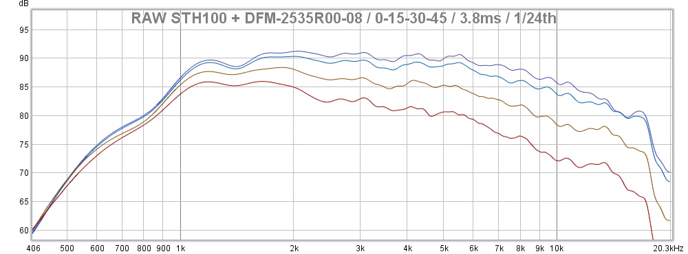
Here's one compression driver/horn combo that's pretty straight-line ( in it's downward slope from 2.5K on up ) for a driver.
These traces done by Zvu ( are from the Peerless DFM-253508 on the 152i Clone from B52 .

🙂
Here's one compression driver/horn combo that's pretty straight-line ( in it's downward slope from 2.5K on up ) for a driver.
These traces done by Zvu ( are from the Peerless DFM-253508 on the 152i Clone from B52 .
🙂
Here's an example where it's not really practical to combine the 2 functions of HiPass with that of Response Flattening .
This "Trace" belongs to "grahamgraham" .
🙂
This "Trace" belongs to "grahamgraham" .
🙂
Kris,
Here's an example of a filter that combines the functions of the HiPass with that of a HF Compensation Circuit ( which flattens the overall HF response ).
This is one of my Peerless drivers on a 152i Clone wavequide.
BTW; R1 + R2 are bypassed here ( iow; they are not in circuit so ignore their presence or values ) ).
- The same "out-of-circuit" observation applies to the 2 pictured PEQ circuits seen ( L4,C4,R4 + L3,C3,R3 ) . They aren't active + are not there ( functionally ).
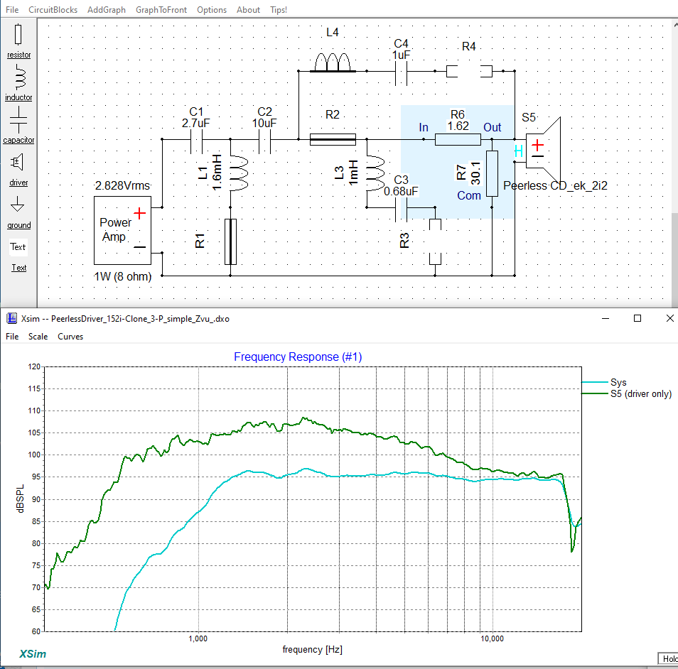
This filter also employs a mild "Bump-Filter" ( at cut-off ) to PEQ boost a small area .
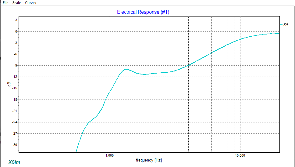
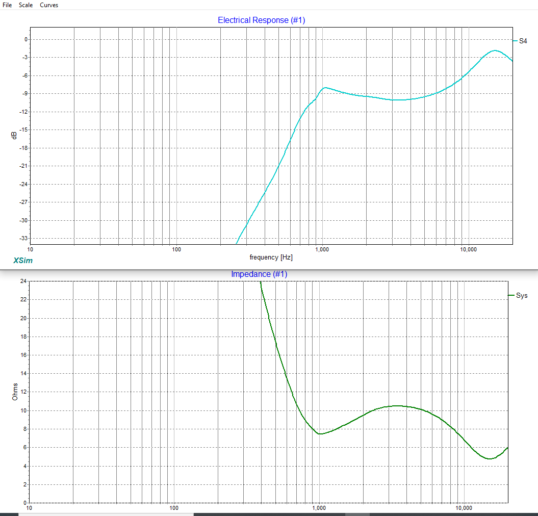
Here's a shot of the filters transfer function.
Again, this combo approach is only doable when the HF response presents a "good-enough" straight line.
These simple horn circuits are quite widely found in many Sound Reinforcement crossovers.
🙂
:
Here's an example of a filter that combines the functions of the HiPass with that of a HF Compensation Circuit ( which flattens the overall HF response ).
This is one of my Peerless drivers on a 152i Clone wavequide.
BTW; R1 + R2 are bypassed here ( iow; they are not in circuit so ignore their presence or values ) ).
- The same "out-of-circuit" observation applies to the 2 pictured PEQ circuits seen ( L4,C4,R4 + L3,C3,R3 ) . They aren't active + are not there ( functionally ).
This filter also employs a mild "Bump-Filter" ( at cut-off ) to PEQ boost a small area .
Here's a shot of the filters transfer function.
Again, this combo approach is only doable when the HF response presents a "good-enough" straight line.
These simple horn circuits are quite widely found in many Sound Reinforcement crossovers.
🙂
:
Attachments

Here's a look at one way to handle the gentle roll-off curve seen in grahamgraham's trace of the Peerless driver on the STH100 waveguide.
Again, C2 is shorted and the LCR notch ( L3,C3,R3 ) isn't engaged.
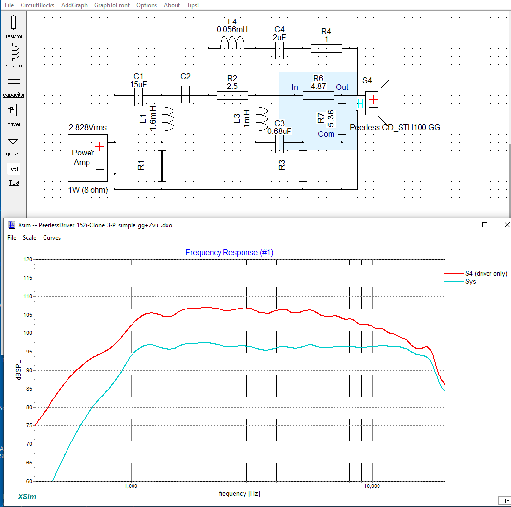
The red curve ( seen above ) is the raw response ( I've used a zma file from my own files to make this happen > so the simulation is only so-so ).
And here's what the electrical filter is actually doing along with an impedance trace.
- Both "Peaking" filters betray their presence ( when looking at the dips in the overall impedance ).
🙂
Again, C2 is shorted and the LCR notch ( L3,C3,R3 ) isn't engaged.
The red curve ( seen above ) is the raw response ( I've used a zma file from my own files to make this happen > so the simulation is only so-so ).
And here's what the electrical filter is actually doing along with an impedance trace.
- Both "Peaking" filters betray their presence ( when looking at the dips in the overall impedance ).
🙂
Attachments
- Home
- Loudspeakers
- Multi-Way
- Combining cross overs