No problem, Joel🙂sori paulo I forgot to change the value.look in my past thread I have mentioned the value.Im using cellphone could not check schematic.
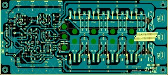
Your're fast! 😉...... another PCB , have fun
Alex .
It's ready for music
Hi,
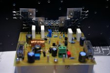
I finished one channel. As I didn't want to drill and tap more holes into the heatsink I used a different approach. Hope it's not a problem.
Electrolytic caps are Panasonic FC/FM. The input cap is off board and is made of 4 paralleled 1uF 400V Evox Rifa PHE450 polypropylene. The low value caps are Wima FKP2 and ceramic (wich in the future will be replaced by silvered micas).
I forget to order 1.5k and 3.6k resistors and solve the issue by connecting in series 1k + 500r and 1.8k + 1.8k. I know, it won't win a beauty contest...
I'm ready to power the amp. The rails will be 36V from a 300VA 25-0-25 Vac toroidal transformer. I'll use unregulated 3 x 6800uF = 20400uF paralleled each rail, and MKP10 100nF Wimas filtering HF noise at the output of the PSU. The diodes have Wima MKP2 100nF across.
The speakers are the same KEF Cresta 10 and the source will be the soundcard and the DVD player. After that I'll use the preamp also (wich is a wonderful PRE4 from Pavel Macura).
Before I test the amp I need to know one thing: what's the bias current I should set?
Hi,
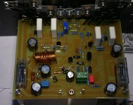
I finished one channel. As I didn't want to drill and tap more holes into the heatsink I used a different approach. Hope it's not a problem.
Electrolytic caps are Panasonic FC/FM. The input cap is off board and is made of 4 paralleled 1uF 400V Evox Rifa PHE450 polypropylene. The low value caps are Wima FKP2 and ceramic (wich in the future will be replaced by silvered micas).
I forget to order 1.5k and 3.6k resistors and solve the issue by connecting in series 1k + 500r and 1.8k + 1.8k. I know, it won't win a beauty contest...
I'm ready to power the amp. The rails will be 36V from a 300VA 25-0-25 Vac toroidal transformer. I'll use unregulated 3 x 6800uF = 20400uF paralleled each rail, and MKP10 100nF Wimas filtering HF noise at the output of the PSU. The diodes have Wima MKP2 100nF across.
The speakers are the same KEF Cresta 10 and the source will be the soundcard and the DVD player. After that I'll use the preamp also (wich is a wonderful PRE4 from Pavel Macura).
Before I test the amp I need to know one thing: what's the bias current I should set?
Attachments
Last edited:
Don't forget the bulb tester - will prevent eventual problems 🙂
Let's hope everything is OK.
Regards!
Let's hope everything is OK.
Regards!
Bad news
I got smoke 🙁
20 Ohms R5 went in flames. I checked to see if I missplaced any part but all seems good with the drawing... 🙁
Can you please help me figuring out where's the problem?
Thanks
I got smoke 🙁
20 Ohms R5 went in flames. I checked to see if I missplaced any part but all seems good with the drawing... 🙁
Can you please help me figuring out where's the problem?
Thanks
do you still have 750 ohm from Q6 base to rail (remove short transistor if short)? 680k actually 680k not 680, Q6 not backward, that sort of thing...
Last edited:
No... but I also don't have any 680k resistor... nor 2sc transistor... I'm using TIP142...😕do you still have 750 ohm from Q6 base to rail (remove short transistor if short)? 680k actually 680k not 680, Q6 not backward, that sort of thing...
There is, however, a 68k resistor from Q3 colector to ground and a 750 ohm from Q3 base to rail.
Attachments
Last edited:
did u change d1 and d12 to murs120
i uploaded two circuit.what differential transistor u used?i have check ksa992 &schematic it is alright.i will still review again what i have uploded usually when my schematic is wrong also the layout.
i uploaded two circuit.what differential transistor u used?i have check ksa992 &schematic it is alright.i will still review again what i have uploded usually when my schematic is wrong also the layout.
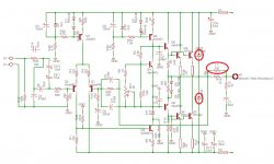
Sorry. Old schem showed ksc2316 in place of Q3 2n5551.
You might have an odd short somewhere, since the current that blew R5 did not come through R35.
It might be time to put a light bulb in series with the transformer primary and start measuring around. (if everything measures okay cold)
You might have an odd short somewhere, since the current that blew R5 did not come through R35.
It might be time to put a light bulb in series with the transformer primary and start measuring around. (if everything measures okay cold)
Last edited:
mpsa92 schematic is ok too.
my software did not report error about clearance so layout is ok.usually my most hardest part in my assembling is isolating the drver and output from heatsink.did you turn the pot at middle before soldering it?how many output did u used sori cannot see pics im using celphone.it should be 2pairs coz the transistor is 100v 10a.
my software did not report error about clearance so layout is ok.usually my most hardest part in my assembling is isolating the drver and output from heatsink.did you turn the pot at middle before soldering it?how many output did u used sori cannot see pics im using celphone.it should be 2pairs coz the transistor is 100v 10a.
Now I see picture.
Hi Paulo,
remove the supply and ground.then remove those 3 metal spacer.put one probe on heatsink and the other probe on each metal of output transistor.do it one by one and also collector of pre driver and vbe transistor.put your dmm range to mega ohms it should be infinite.
Usually when I tighten these transistor very hard sometimes the metal casing of transistor come in contact with heatsink through the hole of this isolation pad.
regards,
joel
p.s.
still checking my schematics and layout still no possible problem i could see.and also check one by one value of resistor.
R5 burned again
I'm frustrated. 🙁I checked resistors, I desoldered all active parts and checked them with the multimeter - all were good except Q3. Then I resoldered everything and checked as drowranger said the insulation with the heatsink. I visualy inspected the board for solder shorts. I also checked the power supply.All seemes ok, except that, again, R5 burst into flames. It took a few seconds before R5 start burning. I was getting 0.8V across R7 and for a few seconds I thought all was fine. Then, R5 burned. I don't know what else could be wrong. I wonder if is something so obvious that because of that I overlooked. I think and rethink and I can't figure it out. I don't know what else to check. Any more ideias?
I'm frustrated. 🙁I checked resistors, I desoldered all active parts and checked them with the multimeter - all were good except Q3. Then I resoldered everything and checked as drowranger said the insulation with the heatsink. I visualy inspected the board for solder shorts. I also checked the power supply.All seemes ok, except that, again, R5 burst into flames. It took a few seconds before R5 start burning. I was getting 0.8V across R7 and for a few seconds I thought all was fine. Then, R5 burned. I don't know what else could be wrong. I wonder if is something so obvious that because of that I overlooked. I think and rethink and I can't figure it out. I don't know what else to check. Any more ideias?
- Status
- Not open for further replies.
- Home
- Vendor's Bazaar
- Combined Onaudio thread. (23 threads)