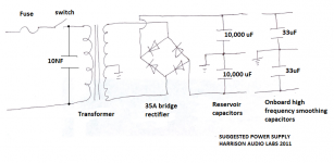
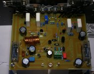
If R26 is alright, your power supply may be having high high frequency voltages. If that's the case Then remove R26 and see what happens
Just in case you got a bad batch of mpsa92 for the differential pair replace them with another set or with the 2N5401
hi paulo
check r10 and r11 in schematic it is ok but in layout the name interchange but the value is correct.
check r10 and r11 in schematic it is ok but in layout the name interchange but the value is correct.
did you notice it?
hi paulo and harrison,
r10 in pcb layout is 100k and r11 is 240 i repeat in pcb layout.but in schematic their names interchange but not the value.sori paulo and harrison for giving you hardtime.
Regards,
joel
hi paulo and harrison,
r10 in pcb layout is 100k and r11 is 240 i repeat in pcb layout.but in schematic their names interchange but not the value.sori paulo and harrison for giving you hardtime.
Regards,
joel
I reported that on post 117:I think he got it right
I noticed in the schematic R10 and R11 are switched but ok in the layout.
More flames and smoke, unfortunately.
I measured R1 = 744.5 ohms and R30 = 220.3 ohms.
I did the following:
- I took out all film caps across the psu;
- replaced R5 and Q3 with fresh parts;
- replaced mpsa92 dif. pair with 2N5401
- disconnected R26
Still the same result. About 30 to 45 seconds after I powered the circuit R5 burst into flames and smoke. Not at imediat power, but almost a minute after power.
Before the smoke voltage across R30 was slowly raising and the last value before the smoke was 517 mV.
Last edited:
Not very good, Harrison. My room smells burnt resistors. 🙁
I opened a window to see if the smell goes away.
I wonder, could it be the wires connecting the power transistors to the pcb causing some oscillation?
I opened a window to see if the smell goes away.
I wonder, could it be the wires connecting the power transistors to the pcb causing some oscillation?
Last edited:
...Also try MJE340 for Q3 ...it might reveal culprit.....Q3 is blowing.....whats causing this ?...it shouldn't happen
Some progress
I soldered C2 and C12 below the board at the transistor pins, between these and to the ground track just above. I replaced Q3 by BD139.
This time, no flames, no smoke, no smell🙂
I measured bias across R7 and the minimum is about 800mV and I can raise it, went to 1V and lowered again. So the bias is working.
I measured DC offset at the speaker terminal and I got 1.44V. No way I'm connecting a speaker!
Now, what should I do/measure next?
R26 is in place.
Here are the voltages:
R30 = 220
R35 = 91
R5 = 22.1
V(R30) = 524 mV
V(R35) = 635 mV
V(R5) = 1.237 V
Here are the voltages:
R30 = 220
R35 = 91
R5 = 22.1
V(R30) = 524 mV
V(R35) = 635 mV
V(R5) = 1.237 V
- Status
- Not open for further replies.
- Home
- Vendor's Bazaar
- Combined Onaudio thread. (23 threads)

