Ok time for a new build thread!
I’ve been planning my InDIYana event “Keeping up with the Jonzes” build for some time and am finally getting splinters from it!
So let’s start with the name, it’s a “coaxial” driver build, or coax, to coax is to be persuasive, these cabinets will be very beautiful and one of my favorite bands R.E.M. have a song called “Pretty Persuasion”. Marketing had a fit over it, they said it was too convoluted so I fired them all and now it’s just me in my garage doing what I want. Makes sense? Alright!
Cost of drivers per cabinet must be under $300 and there are a few other rules as well, check the official thread.
My choice of drivers are the FaitalPro 6HX150 coax ($179 was from online source) combined with the MCM Audio Select 55-5670 8” woofer ($40 each). These model well together and the 8” will have strong response down to 30hz ported and is efficient enough to keep up with the very efficient Faital.


Crossover will be passive as the contest dictates.
Mainly I’m going to be focusing on the enclosure construction for the next few posts. If you’ve been following along my projects over the last year or two, you’ll notice I’m constantly experimenting with new enclosure designs, construction and styles, this project will be no different as I’ll be diving into the world of Kerfing which I’ve never done before.
When I interact with a concept I usually like to do something special with it or something I haven’t seen too much before, and this time I’ll be kerfing solid popular to create a one piece baffle, the enclosure will look veneered but in reality it will be solid wood which I find special/notable.
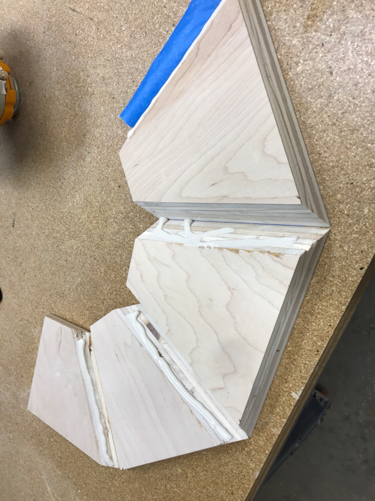
I did a fair amount of testing initially, but this is a piece I did successfully with poplar, my goal here was to determine the optimal kerf depth so that the wood would bend without breaking


This is another test piece, this was more representative of the actual speaker ID building, however it was with plywood, but it gave me an idea of the curve depth with and spacing and what radius curve it would generate. I used an online calculator to get me in the ballpark, then I fine-tuned using this type of experimentation


This is the wood I’ll actually be using For the speakers, as you can see I found two boards so that the grain will be continuous from one speaker to the other from left to right, as you can see the boards are matched across both speakers. This is very beautiful Poplar heart wood.


Cutting the boards to their rough final length, the length is determined by the baffle width, the circumference of the radiuses, and the lengths of the sides.

To create the height of the speaker, these boards were glued together and reinforced with biscuits


The glue up,I used Titebond type III which sets up a little slower in case I want work on the alignment, noticed the clamping techniques ensuring the boards are tight against the clamp bars
Once the glue dried after about 45 minutes, I square one end in my panel saw, them the whole panel in the table saw, I have this set up to cut perfectly square and it does a great job


Getting ready to cut the kerfs, this is a little fixture I built to reference the fence and allow for subsequent fence movements when Kerfing

After the first cut is made, each subsequent cut is spaced 5/16 of an inch using this drillbit, then the next cut is made. Stop block is slid over to the fence and then it’s once again space with the drill bit

And so it goes. The kerfs are all the same distance from each end which locks in the baffle width which will be about 12 inches wide. Kerf depth results in about 1/16” material left.


First board curved and cut, final angle is about 95° which is intentional to gives the sides some rake


Both curves done on both sides, again the middle piece is the baffle and the end pieces are the sides

I created some spacer boards to go in the back to lock in the final dimensions, there will be three for each glue up

Here you can see how perpendicular the assembly is, with some like clapping it’s sits perfectly flat on my workbench

Next up some glue!
Thanks!
Javad
I’ve been planning my InDIYana event “Keeping up with the Jonzes” build for some time and am finally getting splinters from it!
So let’s start with the name, it’s a “coaxial” driver build, or coax, to coax is to be persuasive, these cabinets will be very beautiful and one of my favorite bands R.E.M. have a song called “Pretty Persuasion”. Marketing had a fit over it, they said it was too convoluted so I fired them all and now it’s just me in my garage doing what I want. Makes sense? Alright!
Cost of drivers per cabinet must be under $300 and there are a few other rules as well, check the official thread.
My choice of drivers are the FaitalPro 6HX150 coax ($179 was from online source) combined with the MCM Audio Select 55-5670 8” woofer ($40 each). These model well together and the 8” will have strong response down to 30hz ported and is efficient enough to keep up with the very efficient Faital.
Crossover will be passive as the contest dictates.
Mainly I’m going to be focusing on the enclosure construction for the next few posts. If you’ve been following along my projects over the last year or two, you’ll notice I’m constantly experimenting with new enclosure designs, construction and styles, this project will be no different as I’ll be diving into the world of Kerfing which I’ve never done before.
When I interact with a concept I usually like to do something special with it or something I haven’t seen too much before, and this time I’ll be kerfing solid popular to create a one piece baffle, the enclosure will look veneered but in reality it will be solid wood which I find special/notable.
I did a fair amount of testing initially, but this is a piece I did successfully with poplar, my goal here was to determine the optimal kerf depth so that the wood would bend without breaking
This is another test piece, this was more representative of the actual speaker ID building, however it was with plywood, but it gave me an idea of the curve depth with and spacing and what radius curve it would generate. I used an online calculator to get me in the ballpark, then I fine-tuned using this type of experimentation
This is the wood I’ll actually be using For the speakers, as you can see I found two boards so that the grain will be continuous from one speaker to the other from left to right, as you can see the boards are matched across both speakers. This is very beautiful Poplar heart wood.
Cutting the boards to their rough final length, the length is determined by the baffle width, the circumference of the radiuses, and the lengths of the sides.
To create the height of the speaker, these boards were glued together and reinforced with biscuits
The glue up,I used Titebond type III which sets up a little slower in case I want work on the alignment, noticed the clamping techniques ensuring the boards are tight against the clamp bars
Once the glue dried after about 45 minutes, I square one end in my panel saw, them the whole panel in the table saw, I have this set up to cut perfectly square and it does a great job
Getting ready to cut the kerfs, this is a little fixture I built to reference the fence and allow for subsequent fence movements when Kerfing
After the first cut is made, each subsequent cut is spaced 5/16 of an inch using this drillbit, then the next cut is made. Stop block is slid over to the fence and then it’s once again space with the drill bit
And so it goes. The kerfs are all the same distance from each end which locks in the baffle width which will be about 12 inches wide. Kerf depth results in about 1/16” material left.
First board curved and cut, final angle is about 95° which is intentional to gives the sides some rake
Both curves done on both sides, again the middle piece is the baffle and the end pieces are the sides
I created some spacer boards to go in the back to lock in the final dimensions, there will be three for each glue up
Here you can see how perpendicular the assembly is, with some like clapping it’s sits perfectly flat on my workbench
Next up some glue!
Thanks!
Javad

Sexy even.
“Sexy Persuasion”, the “Persuasion” may be redundant =)
For future builds, you might consider filling the kerf voids with Bondo, to add a little strength and potentially to reduce telegraphing through the veneer.
For future builds, you might consider filling the kerf voids with Bondo, to add a little strength and potentially to reduce telegraphing through the veneer.
Looking more closely, only the strength increase would apply here.
Well I haven’t posted about the gluing yet, so stay tuned. I experimented with several methods and believe I implemented an excellent solution.
mrkennyk said:I hope to attend next year and feast my eyes on those babies.
Sweet!
I tested several adhesives to glue the kerfs including media filled epoxy (was overkill and messy to work with), wood glue(too runny) and Loctite construction adhesive which I ended up using. It was thick and didn’t run, squeezed nicely into the voids to support the “veneer surface”, and had great adhesive strength.
Since the cabinet would be heavily braced, ultimately there will be very little load on the kerfs, I think even with proper construction you wouldn’t even have to glue the kerfs, the bracing and ribs of the enclosure will hold everything to shape. It’s also interesting to note how much spring pressure there is on a kerf like this, it takes substantial pressure the bottom out the kerfs and hold the shape so really gluing is a great idea.


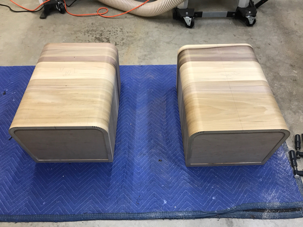
I built some spacer blocks to set the final width out of MDF, and used a combination of straps and bar clamps to hold everything while the glue dried for about three days. After 3 days the clamps essentially fell off and all the spring load of the kerfs was gone, a good sign.


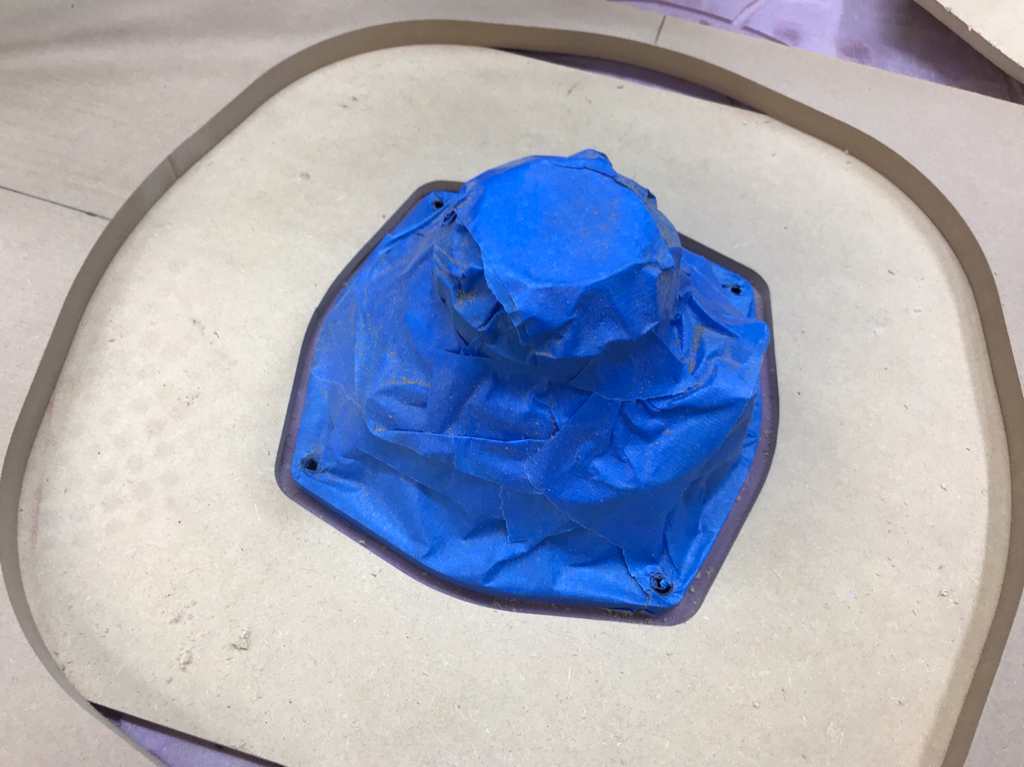
While the glue was drying I decided to work on the midrange sub-enclosure, i used a technique I’ve done before in my Rally Sports and also the 135Hz horn, the reverse horn, The idea being to reduce the number of parallel surfaces and allow the backwave to diffract and be absorbed better than in a simply square or rectangle or enclosure.
An easy way to build one is to cut your parallel top and bottom angles on the tablesaw, for this I chose about 20°, then create a fixture to hold the piece at that angle in the radial chopsaw, and in this case I cut 45° angles to create a three-dimensional trapezoid or a four sided pyramid.


Each time a cut is made the board is flipped and cut the other way

And this is easily glued together with tape


I wanted to add a little more volume and depth so I created a small riser block of 1.5 inches high


To finish it off I added another small deflector at the bottom flat part of the enclosure, just to interact with any higher frequencies


Since my back panels now had angles, I wanted to the square them to each other so I can simply add a back without having to cut any fancy angles. For this I used my handy new cross cut sled that I built, and simply fixtured each enclosure on the sled and easily made the cuts.


Gluing up more panels for the back top and bottom of enclosure

Next up I’ll document the bracing.
Thanks!
Javad
Since the cabinet would be heavily braced, ultimately there will be very little load on the kerfs, I think even with proper construction you wouldn’t even have to glue the kerfs, the bracing and ribs of the enclosure will hold everything to shape. It’s also interesting to note how much spring pressure there is on a kerf like this, it takes substantial pressure the bottom out the kerfs and hold the shape so really gluing is a great idea.
I built some spacer blocks to set the final width out of MDF, and used a combination of straps and bar clamps to hold everything while the glue dried for about three days. After 3 days the clamps essentially fell off and all the spring load of the kerfs was gone, a good sign.
While the glue was drying I decided to work on the midrange sub-enclosure, i used a technique I’ve done before in my Rally Sports and also the 135Hz horn, the reverse horn, The idea being to reduce the number of parallel surfaces and allow the backwave to diffract and be absorbed better than in a simply square or rectangle or enclosure.
An easy way to build one is to cut your parallel top and bottom angles on the tablesaw, for this I chose about 20°, then create a fixture to hold the piece at that angle in the radial chopsaw, and in this case I cut 45° angles to create a three-dimensional trapezoid or a four sided pyramid.
Each time a cut is made the board is flipped and cut the other way
And this is easily glued together with tape
I wanted to add a little more volume and depth so I created a small riser block of 1.5 inches high
To finish it off I added another small deflector at the bottom flat part of the enclosure, just to interact with any higher frequencies
Since my back panels now had angles, I wanted to the square them to each other so I can simply add a back without having to cut any fancy angles. For this I used my handy new cross cut sled that I built, and simply fixtured each enclosure on the sled and easily made the cuts.
Gluing up more panels for the back top and bottom of enclosure
Next up I’ll document the bracing.
Thanks!
Javad
Ok time for some bracing!
I started with a tracing of each enclosure since they vary slightly, this gave me a template for all the other braces. Ultimately I needed a top and bottom brace, a brace for the midrange enclosure and 3 additional braces approx every 4”


Each brace was cut out with a jig saw and finalized to shape in my Wen desk top oscillating sander (love it btw!)


Tracing the midrange enclosure


Port tube plate

Ports are recessed and the ID is purposely undersized so I can flush trim them through the baffle

Here is a vlog I made describing the braces
YouTube
And all glued and finalized braces
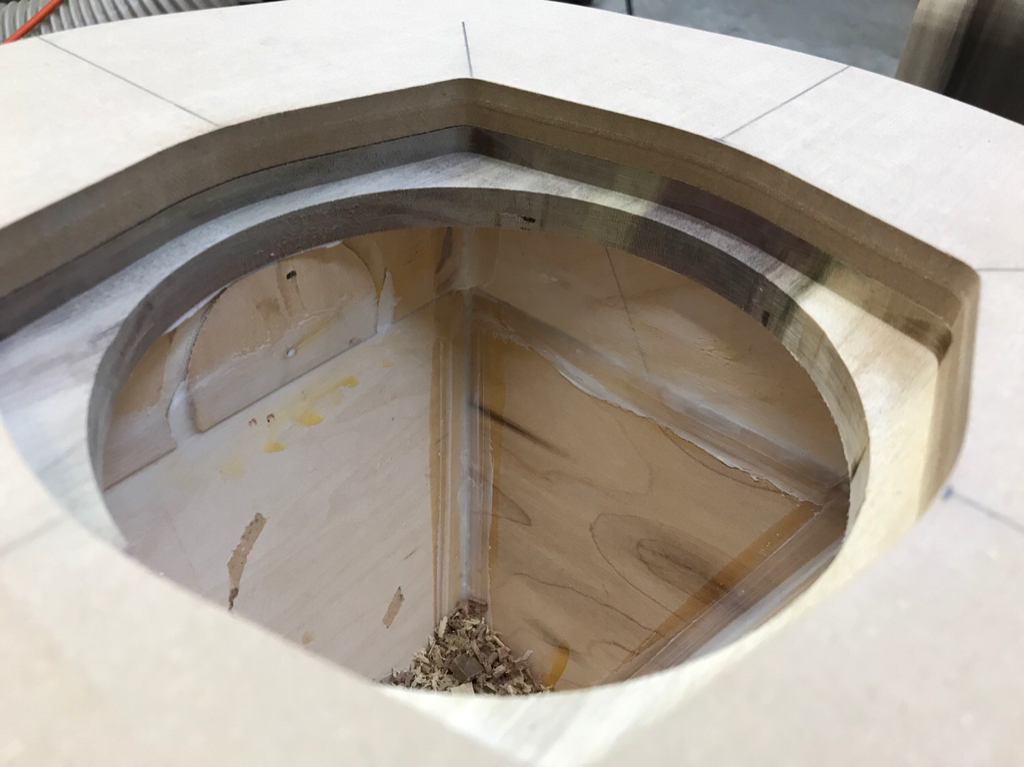
Detail of the mid enclosure


The end caps are spaced 1/8” from the eventual top/bottom for some CLD treatment

Thanks!
Javad
I started with a tracing of each enclosure since they vary slightly, this gave me a template for all the other braces. Ultimately I needed a top and bottom brace, a brace for the midrange enclosure and 3 additional braces approx every 4”
Each brace was cut out with a jig saw and finalized to shape in my Wen desk top oscillating sander (love it btw!)
Tracing the midrange enclosure
Port tube plate
Ports are recessed and the ID is purposely undersized so I can flush trim them through the baffle
Here is a vlog I made describing the braces
YouTube
And all glued and finalized braces
Detail of the mid enclosure
The end caps are spaced 1/8” from the eventual top/bottom for some CLD treatment
Thanks!
Javad
Very nice build.
For others who may try this, I will reiterate the recommendation for Bondo auto body filler. It fills well, is easy to apply and is about one third the cost of the Loctite.
For others who may try this, I will reiterate the recommendation for Bondo auto body filler. It fills well, is easy to apply and is about one third the cost of the Loctite.
Doppler9000 said:Very nice build.
For others who may try this, I will reiterate the recommendation for Bondo auto body filler. It fills well, is easy to apply and is about one third the cost of the Loctite.
Thanks! I’ve got about $12 of Loctite in the entire build (2 tubes) so not bad at all, I didn’t test bondo as it’s more a filler than an adhesive (obviously has adhesive properties) but media filled epoxy worked very well. The amount of spring is tremendous with these kerfs and the Loctite did a great job of holding the shape of the kerfs until I added all the bracing in to completely lock it together.
Appreciate your comments and your following along!
Javad
Time to install some drivers!
This is the layout

As I’ve done before, this is the process for an odd shaped driver Template.
First protect your driver and screw it down to a sacrificial MDF panel, 1/2” works great.

Next with a perfectly centered router base, trace around the frame with a 1/4” spiral bit, put an even layer of masking tape around the driver frame to slightly over size the template

Now on a new sacrificial piece, trace around the inside of the first sacrificial Template

This leaves you with a template 1/4” oversized
Now using a 3/4” Templating fixture, trace around the second sacrificial template to get the final template perfectly sized to the driver


With centering reference lines it is quick and easy to align the fixture on your baffle

Here is a quick blog describing the process: YouTube
Here we have two enclosures ready to destroy, I mean flush mount drivers in! =)
Test cuts finalizing OD, ID and recesses

Marked and ready to go with logic check tracings

Midrange ID cut

8” recess and cutout


Position driver exactly where it needs to go, install fishing line in driver holes

Now with double sided tape on template, slide it over the driver frame and attach it firmly, then pull the driver out. This process perfectly positions the template centered around the driver cutout


Flush trim bit

And router
Test fit

Next port tube routering.
Thanks!
Javad
This is the layout
As I’ve done before, this is the process for an odd shaped driver Template.
First protect your driver and screw it down to a sacrificial MDF panel, 1/2” works great.
Next with a perfectly centered router base, trace around the frame with a 1/4” spiral bit, put an even layer of masking tape around the driver frame to slightly over size the template
Now on a new sacrificial piece, trace around the inside of the first sacrificial Template
This leaves you with a template 1/4” oversized
Now using a 3/4” Templating fixture, trace around the second sacrificial template to get the final template perfectly sized to the driver
With centering reference lines it is quick and easy to align the fixture on your baffle
Here is a quick blog describing the process: YouTube
Here we have two enclosures ready to destroy, I mean flush mount drivers in! =)
Test cuts finalizing OD, ID and recesses
Marked and ready to go with logic check tracings
Midrange ID cut
8” recess and cutout
Position driver exactly where it needs to go, install fishing line in driver holes
Now with double sided tape on template, slide it over the driver frame and attach it firmly, then pull the driver out. This process perfectly positions the template centered around the driver cutout
Flush trim bit
And router
Test fit
Next port tube routering.
Thanks!
Javad
- Home
- Loudspeakers
- Multi-Way
- Coaxial Speaker Build Thread with FaitalPro 6HX150