Usually we use 1k resistors next to the input of FET Opamps.
Do we need this for CMOS Opamps?
If so, is there any change in the value of such a resistor?
What value is then to recommend?
Do we need this for CMOS Opamps?
If so, is there any change in the value of such a resistor?
What value is then to recommend?

It's the same thing, C just stands for Complementary, ie N-ch and P-ch technology combined.
https://en.wikipedia.org/wiki/CMOS
https://en.wikipedia.org/wiki/Field-effect_transistor
https://en.wikipedia.org/wiki/MOSFET
https://en.wikipedia.org/wiki/CMOS
https://en.wikipedia.org/wiki/Field-effect_transistor
https://en.wikipedia.org/wiki/MOSFET
Thanks!It's the same thing, C just stands for Complementary, ie N-ch and P-ch technology combined.
https://en.wikipedia.org/wiki/CMOS
https://en.wikipedia.org/wiki/Field-effect_transistor
https://en.wikipedia.org/wiki/MOSFET
It is what I guessed.
Gate stoppers are already inside chip. Because of usual ESD protection diodes, it is necessary to use input resistors for limiting input current below datasheet specified max. value. In case of OPA1656 and most TI opamps, that is 10 mA. I know from practice that 30 – 50 mA short pulse current doesn’t damage protection diodes.

I am currently working with OPA189 CMOS opamp.Gate stoppers are already inside chip. Because of usual ESD protection diodes, it is necessary to use input resistors for limiting input current below datasheet specified max. value. In case of OPA1656 and most TI opamps, that is 10 mA. I know from practice that 30 – 50 mA short pulse current doesn’t damage protection diodes.
View attachment 1112741
What should you say is a good value of such resistors?
I guess the value depends on what chip we use.
That depends on worst case scenario of input voltages going more than 0.5 V above rails or if input voltage is applied while opamp power supply is turned off. In all cases simple Ohm law will give an answer. Check OPA189 8.3.6. datasheet section. It describes that in detail.
I've burned my share of opamps. 🙂
I've burned my share of opamps. 🙂
Input current max for OPA189 is like you said +/-10mA.
An input resistor of 1k will protect for input rush voltage +/-10V.
Yes it is Ohms law 😀
An input resistor of 1k will protect for input rush voltage +/-10V.
Yes it is Ohms law 😀
We do? Since when?Usually we use 1k resistors next to the input of FET Opamps.
The only resistors I've ever used in series with opamp inputs have been to compensate for the input bias current. That's relevant for bipolar opamps and maybe JFET input opamps. Not relevant for CMOS (= FET) inputs.
When I designed opamps for a living I would include some series resistance for ESD survivability and also EMI filtering.
Tom
I don't think that 10 mA applies to an ESD strike. I'm pretty sure it's a steady-state value.Because of usual ESD protection diodes, it is necessary to use input resistors for limiting input current below datasheet specified max. value. In case of OPA1656 and most TI opamps, that is 10 mA.
Of the three commonly used ESD models, human body model (HBM) is the most gentle on the part. It involves connecting a capacitor charged to a few kV to the pins of an IC through an LC circuit. The L limits the peak current. Even then, the peak current is far beyond 10 mA. The ESD diodes, rail clamp, and power rails on the IC are designed to handle this. There's no need for any added protection outside the IC.
The only exception would be for connections that the end user can touch. So the inputs and outputs should be protected. That's especially true for connections to itty-bitty devices inside of logic gates.
Tom
Yes, it is a steady-state current limit. It was not said otherwise.
FWIW, I had several TI opamps subjected to test, where internal diode had 50 mA / 50 ms long peaks, repeated more than 500 times in a row at 14 s interval, with no ill effect. Later, recognizing design error, I’ve added external diode from input pin to the rail.
FWIW, I had several TI opamps subjected to test, where internal diode had 50 mA / 50 ms long peaks, repeated more than 500 times in a row at 14 s interval, with no ill effect. Later, recognizing design error, I’ve added external diode from input pin to the rail.
I make guitar amps which are customarily abused: inputs/outputs (I´m talking signal level; speaker outs are a wholly different Pandora´s box) where inputs expecting an (electrically) mild signal (less than 1V RMS from high impedance source) (passive Guitar pickup) getting speaker outs, pedals fed from poorly grounded supplies carrying significant voltage differences or grounded to different outlets, sometimes as bad a mismatch as to trigger GFIs, static buildup (Guitar player walking on a nylon carpet on a dry day), leaky pedal or preamp or active guitar coupling capacitors passing significant DC, to boot a normal 🙄 way to turn pedals on is to use a stereo jack with battery negative terminal connected to unused terminal on a stereo jack, so plugging the cable there sends full 9V DC straight to preamp input, the whole catalog of horror stories, and then some.
So at least 33k or 47k are added in series with input pin, clamping diodes are even better.
Increase in noise?
Probably, but a dead amp is even worse,so.
No Idiot proof anything exists, but in over 14000 amps I have had a handful of dead input Op Amps, so protections mostly work.
Of course, "never say never" 🙁
Notice "unused" Ring contact gets 9V battery (or supply) negative.

When a regular Mono guitar plug is half inserted, while plugging in/out, tip gets -9V, body(sleeve gets the other through the pedal circuit.
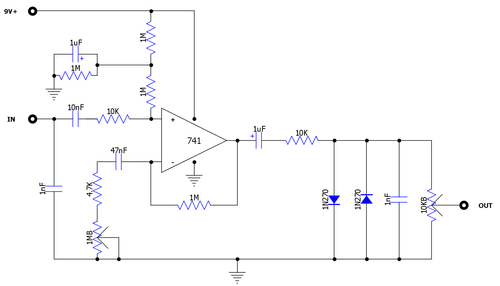
Notice 10k in series with input pin:
So at least 33k or 47k are added in series with input pin, clamping diodes are even better.
Increase in noise?
Probably, but a dead amp is even worse,so.
No Idiot proof anything exists, but in over 14000 amps I have had a handful of dead input Op Amps, so protections mostly work.
Of course, "never say never" 🙁
Notice "unused" Ring contact gets 9V battery (or supply) negative.
When a regular Mono guitar plug is half inserted, while plugging in/out, tip gets -9V, body(sleeve gets the other through the pedal circuit.
Notice 10k in series with input pin:
I used TS912 in my packet radio modem AM7910 based where always some levels of RF @ 145MHz are present. No stoppers nor protection diodes were needed. It is running from 2004 apx several hours a day.
It is good to realize that the purpose of 'gate stoppers' has absolutely nothing to do with limiting input currents.
'Gate stoppers' are used to enhance stability, to avoid oscillations from input pin capacitances and wiring induction.
The resistance should be kept as low as feasible for stability. Values between 10 and 100 ohms are often used, but it is hard to give an absolute value as it depends on the physical implementation and parasitics.
Jan
OPA1656 has 20 Ohm gate stoppers embedded in chip. Probably, many other opamps have them as well, only it is not specified as that is part of internal design.
No wonder no protection is needed. TS912 tolerates 50 mA at input. 🙂I used TS912 in my packet radio modem AM7910 based where always some levels of RF @ 145MHz are present. No stoppers nor protection diodes were needed. It is running from 2004 apx several hours a day.
?????It is good to realize that the purpose of 'gate stoppers' has absolutely nothing to do with limiting input currents.
Jan
I wonder what is R1 doing there. 🤔
In the schematic of post #17, resistor R1 (15K) works with capacitor C25 (100pF) to form a lowpass filter whose -3dB corner frequency is ( 1 / (2*pi*R*C) ) = 106 kHz. This attenuates any radio frequency interference that might be present (even after the ferrite bead L6), and keeps it out of the rest of the amplifier.
Glad to help.
Glad to help.
Agreed. And you can also say that it provides some protection for too high input levels.
But it is not what is commonly understood to be a 'gate stopper'.
Gate stoppers and (in tube country) Grid stoppers are to enhance stability.
If you really want to go into the nitty gritty details (not required to build nice audio amps thopugh):
chrome-extension://efaidnbmnnnibpcajpcglclefindmkaj/https://toshiba.semicon-storage.com/info/application_note_en_20180726_AKX00066.pdf?did=59456
https://www.ampbooks.com/mobile/amplifier-calculators/grid-stopper/
Jan
I know the LMP2021 has some series resistance on its input. I forget which value I used for those. A few hundred ohm maybe. That was done for EMI/RFI reasons.OPA1656 has 20 Ohm gate stoppers embedded in chip. Probably, many other opamps have them as well, only it is not specified as that is part of internal design.
I'm not aware of any opamp that requires external resistors for stability. That's not to say that you can't find one that does, only that I've yet to come across one. Maybe some obscure opamp from the 70s requires them... Not thereby said that you can't make a modern opamp go unstable. It's pretty common that CMOS opamps go unstable when used with large (say MΩ) feedback resistors. That's because of the pole formed by the input capacitance and the feedback resistance. No gate stopper will help you there but a capacitor across the feedback resistor might.
Tom
- Home
- Amplifiers
- Chip Amps
- CMOS OpAmps gate stoppers?