Look at the Apex thread.Hello.I want to add aclipping indicator to my amplifier.It uses +-45.5V rails.
Any suggestions?
Another very good, very simple one is the Leach clipping indicator.
2 transistors, some resistors and a few caps.
There’s a layout on this site The Leach amp 200W amplifier
2 transistors, some resistors and a few caps.
There’s a layout on this site The Leach amp 200W amplifier
Attachments
Last edited:
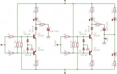
This circuit uses no transistor, and can provide a pre-clipping warning too by correctly dimensioning the zeners (circuit on the right, the LED of U2 is the indicator):
I meant: use a visible LED as an indicator instead of an optocoupler (unless you want to process the information with a microcontroller for example)
Elvee, I am using the Zener approach In one of my commercial amps and it feeds into a uC - works well!
I meant: use a visible LED as an indicator instead of an optocoupler (unless you want to process the information with a microcontroller for example)
Got it..
Thank you all guys for the suggestions.
At what levels should the clipping indicator turn on? For a bjt output stage and +-45V rails should the indicator turn on when output reaches about 40V?is this a good point?
At what levels should the clipping indicator turn on? For a bjt output stage and +-45V rails should the indicator turn on when output reaches about 40V?is this a good point?
Thank you all guys for the suggestions.
At what levels should the clipping indicator turn on? For a bjt output stage and +-45V rails should the indicator turn on when output reaches about 40V?is this a good point?
Amplifier Clipping | The Listening Post Christchurch & Wellington
A quick answer.
An amplifier using +/-50v power supply will be clipping at about 28V RMS.
Attachments
Last edited:
In principle, with "decent" clipping detectors like the ones presented here, it does not matter: the indication is relative to the supply rails, and will adapt itself.Thank you all guys for the suggestions.
At what levels should the clipping indicator turn on? For a bjt output stage and +-45V rails should the indicator turn on when output reaches about 40V?is this a good point?
All you have to do is to decide how close to the rails the output is allowed to go before it is considered as clipping.
The margin is adjustable, thanks to the resistors in the Leach circuit, or the zeners voltage in my circuit.
If you chose a too small margin, the LED will never light, because the amplifier will be unable to swing close enough to the rails. This depends on the amplifier, of course: a MOS amplifier might need several volts.
- Home
- Amplifiers
- Solid State
- Clipping indicator schematic needed