Okay, both driver boards are repaired, they are interchangeable so I tested them in my working left channel.
Ciao collega, come te, anche io sto lavorando su una classe, modello cav180, schema simile al tuo, ho lo stesso problema, non riesco a regolare il bias, e il canale si scalda molto, difetto sulla base del driver, i finali vanno bene, sei riuscito a risolvere il problema?Tagliare il vantaggio dal circuito VBE non ha aiutato molto. Ho rimontato l'amplificatore e il bias continua a non fare nulla. Non ricordo se ho verificato se l'alimentazione del MOSFET è stata attivata o meno. Ho esaminato ancora lo schema e il circuito di protezione del mosfet sembra piuttosto robusto. Non l'ho ancora collegato a un carico. Immagino che forse ho fatto saltare un MOSFET o c'è qualcosa che non va nella scheda del preamplificatore.
In retrospettiva, questa è stata un'idea terribile, ma ho tolto il preamplificatore dal canale buono e sembrava funzionare bene nel canale che stavo risolvendo. Rimettere il preamplificatore buono nel canale buono ha causato un guasto nel canale!!! e il LED rosso sulla scheda del computer proprio accanto alla rete Zobel ha iniziato a lampeggiare quando è entrato in funzione il secondo relè. Ero così arrabbiato.
Ripensandoci:
1.) Avrei potuto danneggiare il buon preamplificatore rimuovendolo o installandolo mentre i condensatori erano ancora sotto tensione. Questo amplificatore impiega alcuni minuti per scaricare i condensatori.
2.) I MOSFET sul canale difettoso iniziale potrebbero essere stati danneggiati e danneggiare il buon preamplificatore.
3.) Forse avrei dovuto sostituire il cattivo amplificatore operazionale associato al computer.
Hello colleague, like you, I'm also working on a class, cav180 model, scheme similar to yours, I have the same problem, I can not adjust the bias, and the channel heats up a lot, defect on the basis of the driver, the endings are fine, did you manage to solve the problem?

Please post in English. Site rules 🙂
Dear DIY friends, my Classe CA 301 amplifier is also sitting on my repair bensch with one defective channel. I have replaced all the defektive NPN/PNP Powertransistors, the Mosfet driver, burned resistors, also replaced the VBe multilpier transistor. Checked all voltages and the powerup sequence of the amp. Hmm, all working fine but as said here before the Bias Adjustment does not work. So i think i have a problem with the 2 constant voltage source circuits with provide the +/- supply to the VBe circuit. I am wondering if anyone here could confirm my reading that the DZ103/104 components are cathode controlled Thyristors ? I am not able to find the DZ103/104 components but i found the ST103/104 which might be same component in a different package? I would very much appreciate if one of the experianced member could provide any hint what replacement components to use in this circuit as also the MPS4250A transistor seams to be out of supply. Thank you very much for reading and for your advice and help. With best regards from Ernst

Dear Patrick
thank you very much for your fast reply and the informations regarding the replacement and the voltages around the DZ103/DZ104 components.
I would have a further question to the voltage levels you are mentioning.
As you say V3/V4 should be arround 2.5V , measured between + / -95V VDC and the base of the Q112 / Q114 transitors.
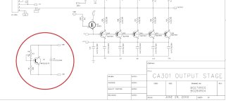
If i understand it right the voltages on the collectors of Transitor Q114 and Q112 are routed out via the connector pins 3/4 and 11/12 to the
VBE MPS2222 Transistor Collector / Emitter and also thrue the 210Ohms (CA301) resistors to the gates of both 10N20 and 10P20 Mosfets.
What voltage should i measured on the Collectors of T114/T112 and on the Emiter/Collector pins of Q1 MPS 2222 Transistor?
I have also a question on the TL431CLP component.
Can i use this Programable Reference component 1:1 at the place of DZ103/104 without any change on the other circuit elements ?
Thank you very much again for your help and advice.
With best regards Ernst
thank you very much for your fast reply and the informations regarding the replacement and the voltages around the DZ103/DZ104 components.
I would have a further question to the voltage levels you are mentioning.
As you say V3/V4 should be arround 2.5V , measured between + / -95V VDC and the base of the Q112 / Q114 transitors.
If i understand it right the voltages on the collectors of Transitor Q114 and Q112 are routed out via the connector pins 3/4 and 11/12 to the
VBE MPS2222 Transistor Collector / Emitter and also thrue the 210Ohms (CA301) resistors to the gates of both 10N20 and 10P20 Mosfets.
What voltage should i measured on the Collectors of T114/T112 and on the Emiter/Collector pins of Q1 MPS 2222 Transistor?
I have also a question on the TL431CLP component.
Can i use this Programable Reference component 1:1 at the place of DZ103/104 without any change on the other circuit elements ?
Thank you very much again for your help and advice.
With best regards Ernst
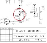
1. The purpose of testing V1 and V2 voltages is to confirm the first input and driving transistors are ok or not. Reading V3,V4 voltages is to confirm the parts DZ103/DZ104 ok or not, if all voltages ok then these parts are ok.
2. You should check what exactly the parts on your PCB for these DZ103/104, are there any part number on them, are they three pins same as TL431CLP, or they are just TL431CLP, you need to find out.
3. The voltage measured on the Collectors of T114/T112 is just the MPS 2222 VBe circuit voltage +Dr -Dr, you can get the voltage range simple by VBe circuit calculation with the resistor R2 (383 Ohm) and R3 VR( take half resistance value of R3 to calculate). Or you can just carefully to check it from the other good channel.
Attachments
Hallo Patrick
thank you very much for the further help and clarifications.
I have dismantled the complete left channel of the CA301 amp again and will now setup the channel outside of the amp chassis
on my workbench, so i can do the measurements on the GainsStage PCB.
The components DZ103 / DZ104 are marked as AS431 Precision Shunt Regulators.
From a short comparision of the datasheet paramenters the AS431 seams to be compatible with the TL 431.
I am anxiously looking forward to what failure i will find and whether i am able to fix the issue.
With best regards Ernst
If you tested all the parts again and all parts seems ok but just can't adjust the Bias. You may try adding two 47pF 200V normal round disc ceramic capacitor at the final Mosfet drivers, solder them close to the Mosfet pins, pins of +V1 / -V1 to the gate pin.
Attachments
Hello Patrick
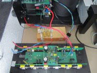
i have in the meantime made-up a better test cableing so i can measure the defect channel on my workbench.
Picture attached.
I also added 2.2Kohm resistors from the +/-power rails to ground for a faster discharge of the powersupply.
Courious to see how far i will come in find and fix the problem.
Best regards
Attachments
Careful to check again the connections between the different sides after we replacing a part in a double sided PCB
Hallo Patrick
i have ordered and received the transistors MJE340/350/MPSA18 and the AS431.
Was not able to find the MPS4250 so i strived for a equivalent and found the 2N5087 ? which i used.
I carefully replaced all the old components on the PCB.
I switched on the amp and measured as you recommend the Test Point voltage situation aginst +VDC / -VDC.
Here is what i found.
TP6 3.57V
TP4 2.91V
Base of Transistor Q114 was 1.37V may be bit low ?
TP5 3.81V
TP3 3.08V
The Voltage across (+DR -DR C/E) on the VBE Multiplier MPS 2222 Transistor was now adjustable and
i adjusted it similar to the working right cannel value at 2.2V.
So i thought i am a happy camper, but nothing at all happed to the Bias current, still 0.00Amps
Hmm i am puzzled.
Via the 14Pin connector both voltages +DR1 (pin 3/4) and -DR1 (pin11/12) are
routed to the Diode/Zener/ 3 Resistor circuit to become
SS1 connected to the Base of the NPN transistors (i measured 0.05V to ground) and
S1 connected to the Base of the PNP transistors ( i meassred -0,45V to ground)
Could it be that either the Diode D1 or the D4 3.3V Zener going to SS1 are defektive ?
Looks like that i have to find the problem with the missing voltage on the Base of the NPN transistors.
Any hints where to look ?
Thank you very much again for reeding above description and you help and effort to finally
find the issue.
Best regards Ernst
Dear Patrik
I have one additional question.
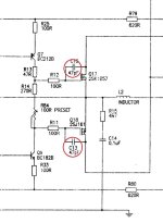
There are this 3 resistors R5/R6/R7 sitting between the D4Zener Anode/Signal SS1 and ZenerD3 Cathode/Signal S.
The values of this 3 resistors in the Classe CA301 schematics is marked as 300. Is this Ohm, KOhms ?
Unfortunatelly i can not regognize the rings color on the resistors.
Thank you for your help.
Best regards Ernst
I have one additional question.
There are this 3 resistors R5/R6/R7 sitting between the D4Zener Anode/Signal SS1 and ZenerD3 Cathode/Signal S.
The values of this 3 resistors in the Classe CA301 schematics is marked as 300. Is this Ohm, KOhms ?
Unfortunatelly i can not regognize the rings color on the resistors.
Thank you for your help.
Best regards Ernst
Dear Ernst,
1. Your Test Point voltage reading seems not correct, according to service manual, TP4 should higher than TP6 by 0.6V ( Q113 VBE voltage), so as TP3 > TP5 0.6V. If the Test Point reading exchanged, it seems the voltages reading are ok for the input circuit.
2. The cascade transistors Q114 and Q112 base pin should be around 5V reading which provided by the AS431, if the reading is no correct, pls. check each AS431 and the resistors connected to them R124 & R120 ok or not.
3. Pls. check each power output transistor's emitter resistor is ok or not, otherwise you can't measure Bias voltage on a opened emitter resistor.
4. When we are checking the Bias voltage, we should measure voltage between +DR1 & -DR1, SS1 & S1, not to the ground. * In normal condition, SS1 & S1 voltage should be around 1.2V for the power output transistors to Bias correctly ( when NPN & PNP turns on, each VBE is around 0.6V)
5. Diode D1 and Zener Diode D4 form a clamp voltage protection for the driver MOSFET in +DR1, so as D2 & D3 do the same in -DR2 , you can simple test them ok or not by a multimeter.
Please study and test you amp circuit again
B.rgds
MPS4250 a equivalent 2N5087 is ok. For the pre-driver pair transistors MPSA18 and MPS4250 , can be also replaced by BC550, BC560 (but different pins arrangement), they are the same low voltge low noise
Correction for my previous reply, "2. The cascade transistors Q114 and Q112 base pin should be around 2.5V reading which provided by the AS431"
A 2.2V across (+DR -DR C/E) on the VBE Multiplier MPS 2222 Transistor seems a bit low, the voltage should be over 2.4V. Please test your right cannel Bias to see if you need adj.
Dear Patrick
thank you very much for your immediate reply with the many good informations, hints and tips.
I did not recognize that the three 300Ohm resistors where faulty. They looked a bit brown but they seamed to be OK. But all burned.
The 2 diodes measure OK, the 3.3V Zener are defektive.
All 10 emitter resistors are at 0,37Ohms.
I will now wait for the ordered resistors and zener diodes and then again check the voltages on the testpoints you mentioned and also compare
them to the functional right channel.
Best regards Ernst
- Home
- Amplifiers
- Solid State
- Classe CA-401 Rebuild