Hello audio freakz,
This thread is about my plasma arc speaker.
Wich i had lots of issues with to begin with.
- Overall distortion (over excited feedback by rf scrambling my electronics)
- Overheating buck converters
- Hooking up any digital device without frying it
Lots of problems to solve and it has been a ride.
It finally got down in 2 parts.
A dc voltage opperated tesla coil kinda device to produce the arc.
And a Class D amplifier to supply that tesla coil.
For the tesla coil i went for a resonant gate base fed resonator running at 10.87mhz
And for the audio i went for a Class D amp switching at 80khz.
Heres 2 video's of the device running.
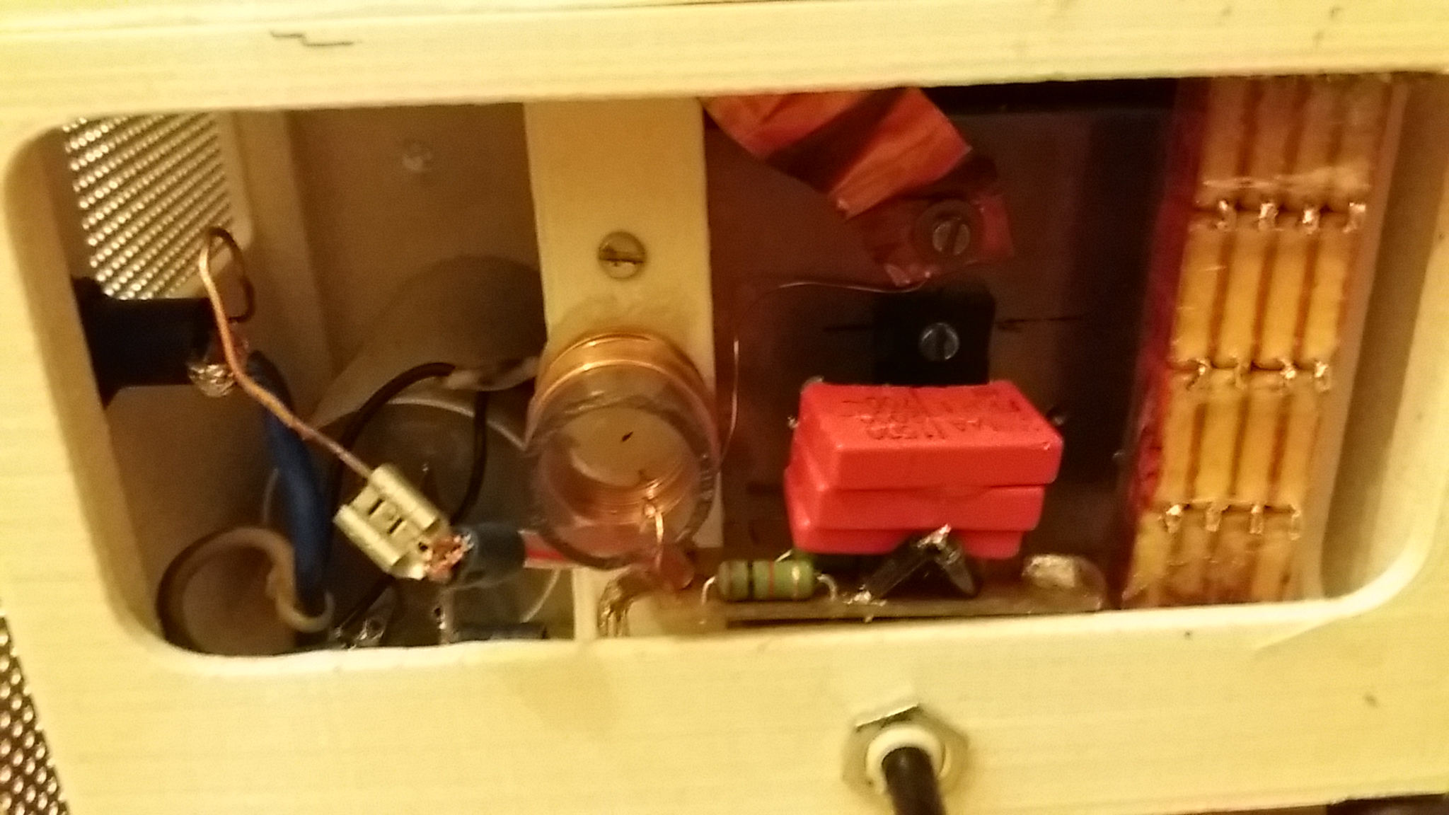
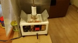
Ill add some picture later on showing the various components (and yes most of the modulator is still on breadboard (and that is not so good for operation that why the rf shield is there to block)
YouTube
YouTube (at the end of this video youll ill show you the setup quick)
Happy to awnser any questions to my build.
Greeting
Jeroen van Dijk
This thread is about my plasma arc speaker.
Wich i had lots of issues with to begin with.
- Overall distortion (over excited feedback by rf scrambling my electronics)
- Overheating buck converters
- Hooking up any digital device without frying it
Lots of problems to solve and it has been a ride.
It finally got down in 2 parts.
A dc voltage opperated tesla coil kinda device to produce the arc.
And a Class D amplifier to supply that tesla coil.
For the tesla coil i went for a resonant gate base fed resonator running at 10.87mhz
And for the audio i went for a Class D amp switching at 80khz.
Heres 2 video's of the device running.
Ill add some picture later on showing the various components (and yes most of the modulator is still on breadboard (and that is not so good for operation that why the rf shield is there to block)
YouTube
YouTube (at the end of this video youll ill show you the setup quick)
Happy to awnser any questions to my build.
Greeting
Jeroen van Dijk
Last edited:
As i am still working on the unit some things are really slapped together but seem to work 🙂
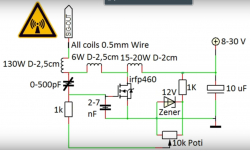
The high frequent solid state tesla coil has a resonant frequency of 10.87mhz.
I used a modified version of the schematic put up by teslaundmehr (youtube).
Wich looks like this.
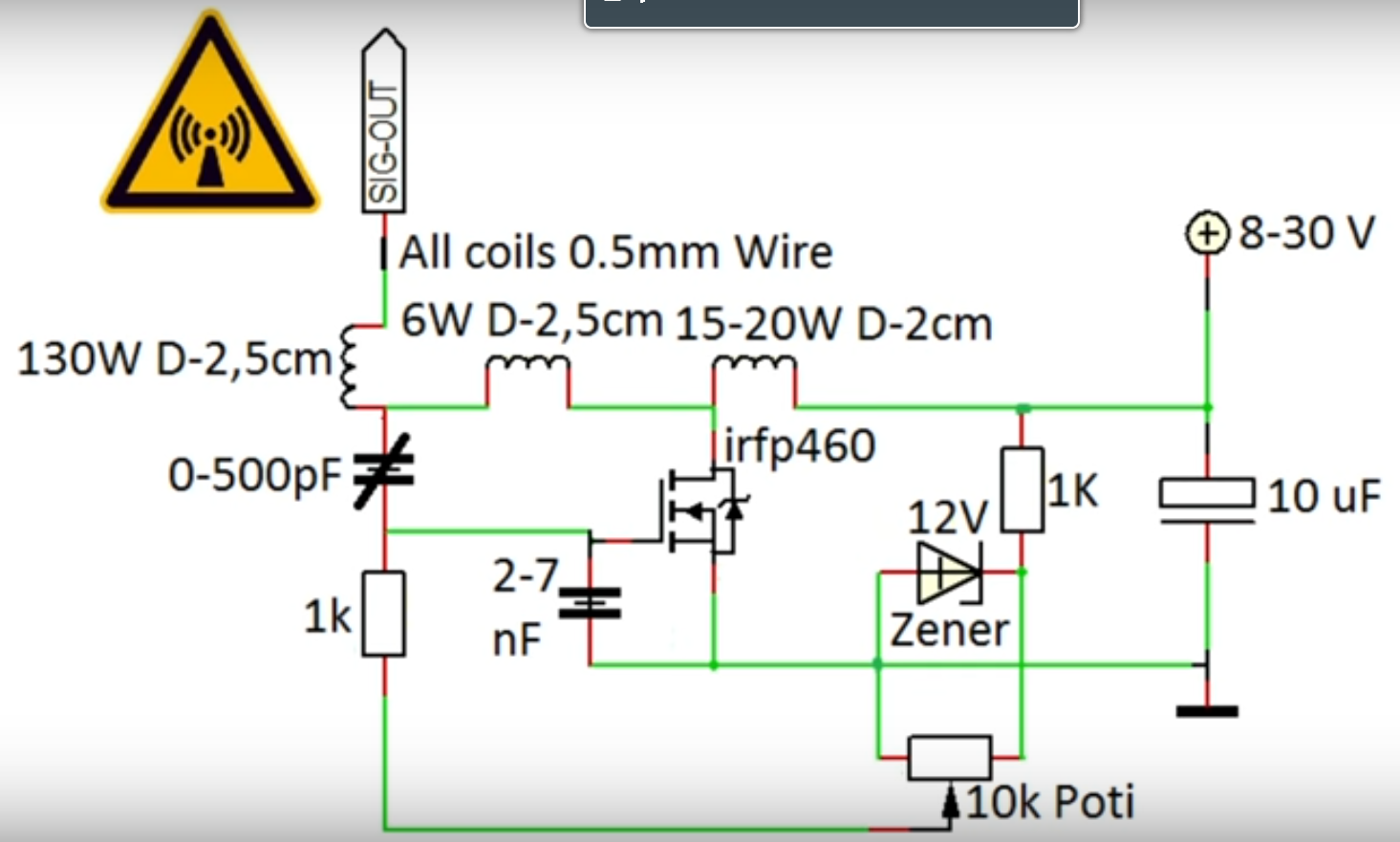
For instance i ditched the variable capacitor and replaced it for a fix mmc.
I added a couple of plates to the mosfets drain wich seemed to increase feedback quite a bit.
My peak input voltage is about 52vdc on the video's, i have tested input voltage till 65vdc.

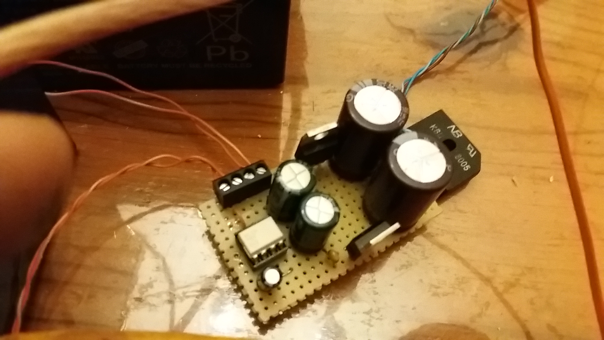
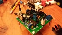
The audio modulator i made for the device is made out of a few building blocks.
- Triangle Osc.
- Triangle Preamp + Buffer
- Bluetooth audio module
- Audio filter/preamp + Buffer
- High speed comparator
I used parts like tl072, opa227, 40106, tl3016.
The bluetooth audio module was a cheap module bought from internet.

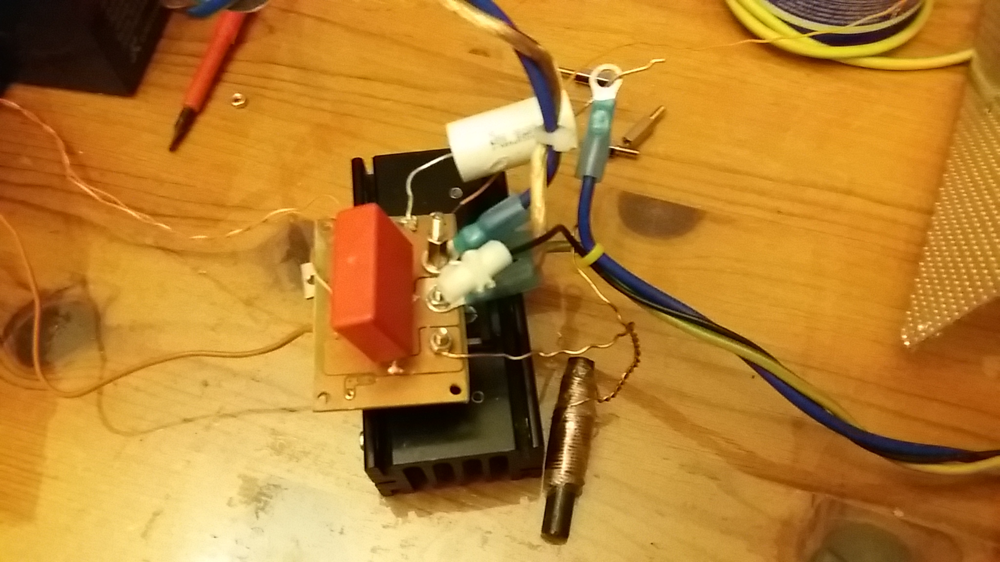
The buck converter consist of a single switch (igbt fgh60n60) cutting the dc at x frequency pwm thats provided as a singal to a fod3184 opto isolated gatedrive ac.
The fod ic has its own transformer to supply for a positive and negative rail.
The output of the igbt is passed through a LC lowpass filter to translate the pwm into a useable voltage for the HFSSTC.
(This is still the protoboard same goes for the buck switch)
I did like to hear some of your oppinions. (and yes i know theres allot of ozone production in these build =) )
Greetings Jeroen van Dijk
The high frequent solid state tesla coil has a resonant frequency of 10.87mhz.
I used a modified version of the schematic put up by teslaundmehr (youtube).
Wich looks like this.
For instance i ditched the variable capacitor and replaced it for a fix mmc.
I added a couple of plates to the mosfets drain wich seemed to increase feedback quite a bit.
My peak input voltage is about 52vdc on the video's, i have tested input voltage till 65vdc.
The audio modulator i made for the device is made out of a few building blocks.
- Triangle Osc.
- Triangle Preamp + Buffer
- Bluetooth audio module
- Audio filter/preamp + Buffer
- High speed comparator
I used parts like tl072, opa227, 40106, tl3016.
The bluetooth audio module was a cheap module bought from internet.
The buck converter consist of a single switch (igbt fgh60n60) cutting the dc at x frequency pwm thats provided as a singal to a fod3184 opto isolated gatedrive ac.
The fod ic has its own transformer to supply for a positive and negative rail.
The output of the igbt is passed through a LC lowpass filter to translate the pwm into a useable voltage for the HFSSTC.
(This is still the protoboard same goes for the buck switch)
I did like to hear some of your oppinions. (and yes i know theres allot of ozone production in these build =) )
Greetings Jeroen van Dijk
Attachments


Thank you for posting these details, This stuff is just Too Cool !!!
And also..... Welcome to the Forum !!! 😀
jer 🙂
And also..... Welcome to the Forum !!! 😀
jer 🙂
- Status
- Not open for further replies.