I have a general question about class D amps like hifonics,emphaser ground zero and so on...
is the square wave signal,which comes from the driver board still present at the gate connection point if i remove all of the output transistors from the board?
or stops the driver board working without connectet Mosfets?
is the square wave signal,which comes from the driver board still present at the gate connection point if i remove all of the output transistors from the board?
or stops the driver board working without connectet Mosfets?
There is no answer that covers all of those amps. For self-oscillating amps, you may get a square wave if you drive a signal into the amp but to get both high and low-side signals, you may have to make other changes (which would be specific to the circuit used in the amp being repaired).
do you have an example for a self-oscillating hifonics amp?what about the amps with the IR21844S driver chips on the driver board?
my actuel problem is a hifonics brutus bxi 8000d.it is using these chips
my actuel problem is a hifonics brutus bxi 8000d.it is using these chips
If the outputs are out of the amp, you should be able to drive a 100HZ (or close) signal into the amp and get a low-side signal on the low-side gates. To get the high-side, you may have to provide an isolated (from ground) power source. I use a 9v battery. Then you may have to ground the high-side FET source pad to view the gate drive signal.
You have to be very careful because there will be high voltage on the high-side drain and the low-side source pads. Those are connected to the rail caps.
If you use a 9v battery, you should insert some sort of over-current protection. A 1 ohm 1/8w resistor would work. A 1 amp fuse should also be OK. The negative side of the battery will go to VS terminal. The positive to the VB terminal. You can make the connection on the ceramic cap connected to VS and VB.
now i installed a brand new driver board,but in two banks,(low and high side from the first driver ic) the mosfets still burn.
the other two banks (low and high side from the second driver ic)dont burn.
now the outputs are out of the amp again,and i measured a little bit.
rail at the caps is 264V (+-132V)
between D and S on the low side 114,1V
between D and S on the high side 149,9V
is this possible?
the other two banks (low and high side from the second driver ic)dont burn.
now the outputs are out of the amp again,and i measured a little bit.
rail at the caps is 264V (+-132V)
between D and S on the low side 114,1V
between D and S on the high side 149,9V
is this possible?
Did you check the output drive waveforms before powering the amp up (with outputs and/or rectifiers?
no,because i was sure that the amp will work with the new driver board.
when i measure at the speaker terminal,there are 18 volts(whithout the outputs)
when i connect a speaker,it is cracking at the speaker.
then i measured the current flow at the speaker terminals.it is 10 mA
where does this come from,with no outputs?!
when i measure at the speaker terminal,there are 18 volts(whithout the outputs)
when i connect a speaker,it is cracking at the speaker.
then i measured the current flow at the speaker terminals.it is 10 mA
where does this come from,with no outputs?!
If you use a 9v battery, you should insert some sort of over-current protection. A 1 ohm 1/8w resistor would work. A 1 amp fuse should also be OK. The negative side of the battery will go to VS terminal. The positive to the VB terminal. You can make the connection on the ceramic cap connected to VS and VB.
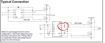
You mean this points?
Attachments
100%confirm you don't have a shorted inductor or the inductor coils rubbed through silkscreen shorting out to supply rail or wherever.I had everything perfect once,drive signals everything.Even checked the inductors in circuit and all 4 were fine.You may have 2,doesn't matter.
After time I fired it,boom all bad.Months later found an inductor rubbed through silkscreen and shorted to the +rail trace I believe.Lots of wasted money on that job.Inductor checking is very important because there generally installed poorly on practically every amp design.
Over time I have found ways to start the amp more or less with reduced chance for unexpected output explosion.Regardless 21844 amps have to be carefully checked or plan on losing on the quote you gave the customer.
Ps the small inductors and I think 1 ohm resistors in the vs path? Check those twice.Serious problems when that 1ohm(I believe it's 1) drifts to 10ohm~ also the small typically green inductors is a another problem I've heard of.Have seen the feedback resistor(1ohm) loose tolerance(wish I had one here to refresh myself).But when you have output/driver failure that resistor I think ends up between vs and have to look it up but it can get a large load on it and never split or burn.
I've seen it 3,4,5 ??times..it can burn you...check absolutely everything in the drive,return,protection path.Just check it all...or take the 24n40 and 21844 and toss em so they don't blow in your face...Kidding,just be thorough,just letting you know what's burned me good.
Ps pk6?? Transient supressors are almost a guarantee to be shorted if amp let loose entirely..check everything.Youll find something you weren't expecting most likely
bxi8000d
Did you manage to fix the amp? i have same amplifier and have problems with it... i extracted all the fda59n30 output transistor and the amplifier is not in protection mode, i even here the relee crancking when i supply the remote 12v, Problem is i don't trust it to put new output transistor in it... smth still seems wrong.. i measured on the speaker output terminals and i have 11.9v dc voltage and rising to 13.1, is this normal?
You mean this points?
Did you manage to fix the amp? i have same amplifier and have problems with it... i extracted all the fda59n30 output transistor and the amplifier is not in protection mode, i even here the relee crancking when i supply the remote 12v, Problem is i don't trust it to put new output transistor in it... smth still seems wrong.. i measured on the speaker output terminals and i have 11.9v dc voltage and rising to 13.1, is this normal?
Old topic...but:
You can try with just one mosfet in each bank, and testing without load. And measure first on the gatesresistors the squarewave signal (only on the low side), without the mosfet mounted.
Do you have audiosignal on the input of the driverboard?
You can try with just one mosfet in each bank, and testing without load. And measure first on the gatesresistors the squarewave signal (only on the low side), without the mosfet mounted.
Do you have audiosignal on the input of the driverboard?
Last edited:
Old topic...but:
You can try with just one mosfet in each bank, and testing without load. And measure first on the gatesresistors the squarewave signal (only on the low side), without the mosfet mounted.
Do you have audiosignal on the input of the driverboard?
Unfortunally i don't have an oscilloscope to measure.... i have exactly the same simtoms as in this post thats why i asked if he found the fix.
- Status
- Not open for further replies.
- Home
- General Interest
- Car Audio
- Class D driver board