...
Personally I'm waiting on the SMPS to be completed.
I am waiting on that too, but I can tell you I was pleasantly surprised with the 500W (bridge) module fed by a linear power supply.
Once the SMPS is available, my intention is to buy another 500W module for comparison.
I also got a SMPS from CNX (Connexelectronic) and will be testing my ClassDAudio module with it very soon.
Cheers!
Originally Posted by tinitus View Post
We should rather talk about the modules, please
I agree with Tinitus, focusing on the modules would be of prime benefit to everyone. It is sad to see so many threads deteriorate into pointless arguing over such trivial and non-relevant matters.
I also hope Tom is not discouraged for participating, I believe there would be many people here that would be interesting in whatever information he could provide in regards to his modules.
I myself appreciate the first hand information given by those who have the units such as Mark and 5th Element, and would like to hear more from them in regards to their units.
Is anyone planning any upcoming tweaks or mods on them?
Also in regards to using switch mode power supplies, I understand that they are capable of sending quite a bit of noise back into the power mains. Would this be of possible concern as it may have an effect on other audio components?
Mike
Well, you may return the modules, and buy new ones costing twice as much, and get stuck with those, happy or not
Anyway, I dont see any EU people getting involved in returning any modules
Tell me, how will you get the custom fee and taxes refunded, or return shipping
Besides, so far everyone seems happy with these amp modules
Why do you argue about a money back offer, that noone else will give you
You know the "rules" of DIY, either it works, or it doesnt
Its all about buying modules that work
And deal with serious people with a minimum of responsibility
Way more important than any money back policy
And one reason why we are here, to share all info and insight
We should not debate how a company handle their economical affairs, as long as they are fair and honest
We should rather talk about the modules, please
+10
Well exactly I don't know why anyone would bring up the 7 day return period at all. I just thought it unfair for someone to knock the company, that are after-all offering a lot more then others.
Personally I'm waiting on the SMPS to be completed.
I think the 7 day return is fair game. I hardly consider criticizing the return policy as 'knocking'. It's called feedback. And I don't think the issue relates to people who have bought the modules but to the probability that ClassDAudio has turned off quite a few *potential* customers because of this policy. Let me say. I am completely happy w/ my amp and I think it is very well made and pretty easy to put together. Tom has been very responsive to questions and very helpful. But I remember being VERY turned off by the 7 day return policy because usually this is a sign of an unreliable product/seller. Also, yes, I was stressed because I knew I had to have my ducks in a row to test it out in time. The only reason I took the leap is because I live close by and knew that it would only take a day to return anything.
Let's be realistic, when it comes to diy it's hard to get a project done in that short a time if you have a life. Even if it's a kit. Very hard. It's part of the experience. You had no problem? Well, good for you. But I don't think most diy'ers would take that policy seriously. Also I don't understand the logic of 'I'm sure they'll take it back after the 7 days if you contact them' mentioned in another post, you can't speak for ClassDAudio and this statement is at best misleading.
The amp I purchased is stellar, the customer service has been great in terms of response, so I do hope they extend the 7 day return policy as I bet it limits sales.
Some people may be rich enough to throw hundreds of dollars on a purchase and say 'well that's the risk you take', but some of us also believe that feedback is good and any effort to minimize doubts of reliability can only help both poth parties.
but hey, that's just me 🙄
Also I don't understand the logic of 'I'm sure they'll take it back after the 7 days if you contact them' mentioned in another post, you can't speak for ClassDAudio and this statement is at best misleading.
Yes I was meaning if you took 10 days due to some unforeseen crap that showed up, they might be willing to still take the amp back. Don't get me wrong here I am not speaking for the company but simply predicting what could be a possibility, considering their helpful nature.
You had no problem?
I wouldn't say that, I had teething troubles with mine. But I didn't buy from ClassD, I designed and etched the PCBs myself based on TIs datasheets. I accidentally destroyed a couple of chips, but at least I know why! 😛
The protection circuitry that stops the H bridges from blowing up seems to only be active when the +12V side of the chip is powered up.
The output stage only turns on if it's got a bit more then 14 volts being delivered to it.
When you remove power the 12V side switches off and the caps quickly drain to a point, but stop draining when the voltage reaches a switch off point.
I had assumed that the caps would drain quickly down to nothing. But apparently not, the residual charge left in the caps was enough to blow the H bridge for one channel when I accidentally shorted something with the power off.
This would explain why some people have reported the chips fail if you only apply voltage to one side of them. It's possible that it's very easy to fry the Hbridge and if anything is amiss with the construction, simply applying power to the Hbridge side alone could cause it to blow up.
This is also the only explanation I can find as to why I managed to blow up a couple of chips also. TI state that the Hbridges are protected from over current, under current, short circuit of the outputs to one another, short circuit of any of the outputs to ground and short circuit to any of the outputs to the power rail. In other words pretty much indestructable, but maybe the protection might not work with the 12V side inactive.
Last edited:
I myself appreciate the first hand information given by those who have the units such as Mark and 5th Element, and would like to hear more from them in regards to their units.
Mine is self made, as I have explained a couple of times already throughout the thread. I use mine to power the bass section of my loudspeakers. This is basically a pair of Peerless XLS 830452s on an open baffle in push-pull configuration, just like in Linkwitz's Orion.
Currently the output inductors that I've got aren't brilliant and distort quite badly at higher frequencies at decent power levels. However the measured performance from 100hz and down is respectable, even right up until clipping.
I briefly listened to them on a pair of passive loudspeakers and liked what I heard, but I would rather re evaluate the conclusions I made once I've got some good output inductors.
I wanted to wind my own using ferroxcube's gapped ferrite cores, but they are seemingly impossible to source. I've posted in the Inductor Evaluation Help thread, but I've yet to have any response, which isn't surprising considering the time of year.
In my application I couldn't be happier. The PBTL version on bass sounds great, I've not nothing to complain about.
Is anyone planning any upcoming tweaks or mods on them?
Mods in line with the standard fare found on DIYaudio are certainly possible.
There will be a few caps in the signal path that no doubt people would want to upgrade, or try and remove. I wouldn't risk removing them however, I don't know how the inputs on the TAS5630 chip would respond to DC.
The regulated line that feeds the input differential opamps could be 'improved', by replacing the 12V feed with any of the supposedly superior regulators found on DIYaudio. Some people might go so far as wanting to provide individual regulators for the different parts of the circuit.
Opamps usually perform better when driven with greater voltages. The OPA1632s are working from a single supply too, meaning they are running off an equivalent of +-6 volts. This isn't particularly high and you could power them off something like +30 volts instead.
So from that stand point I might be interested in providing a +30volt line for the OPA1632s and keep the +12 line the boards already have for the low voltage side of the TAS5630 and the fan control circuitry.
The large caps on the output filter some people might want to replace with some boutique loudspeaker filter caps.
Then there's the output inductors, which I wouldn't recommend touching unless you can measure that the performance of the amp is actually improved by replacing them. This requires you have the ability to measure the differential output of the TAS5630, IE summing the signal from the +ve and the -ve outputs as the TAS5630 works in a bridged configuration. You will also need to have dummy loads so that you can measure the performance of the amplifiers under heavy load.
I would have expected ClassD to use nice output inductors anyway so it's probably pointless to replace them.
Also in regards to using switch mode power supplies, I understand that they are capable of sending quite a bit of noise back into the power mains. Would this be of possible concern as it may have an effect on other audio components?
Mike
I suppose this depends on your view of such things. Any decent power supply fitted to audio equipment should have a decent mains filter fitted anyway. This should remove some of the high frequency gubbins a switchmode might inject. On top of this a standard transformer should be pretty good at isolating any mains borne noise from the system. You've then got the PSRR of the circuit itself to take into consideration, which is usually decent at the frequencies a SMPS would switch at.
You can also have noise injected onto the earth/ground, but I'm not entirely sure how that would affect things.
Here we see a pointless post. Evidently you had a worthwhile point but couldn't express it in a sentence, or just thought you were on digg.
Well, you may return the modules, and buy new ones costing twice as much, and get stuck with those, happy or not
Anyway, I dont see any EU people getting involved in returning any modules
Tell me, how will you get the custom fee and taxes refunded, or return shipping
Besides, so far everyone seems happy with these amp modules
Why do you argue about a money back offer, that noone else will give you
You know the "rules" of DIY, either it works, or it doesnt
Its all about buying modules that work
And deal with serious people with a minimum of responsibility
Way more important than any money back policy
And one reason why we are here, to share all info and insight
We should not debate how a company handle their economical affairs, as long as they are fair and honest
We should rather talk about the modules, please
For every reasoned opinion there are 12 apologists handing out blinders. Are ideas such a threat to you that you must advocate we not have any? Don't get me wrong here but, I've never seen a cheerleader head the debate team. I'll agree with you on one point though, it is about buying modules.
5th, that sounds like a lot of work for seven days to see what it is really capable of? As described by you it sounds perfectly ordinary in stock dress. It takes more than seven days for the ear to tune into that too, and perhaps that's another reason. I'm not buying that whole spiel about expecting them to test it, because what I would expect is a brand spanking new, untouched, unbuggered module. Failing that, "refurbished" comes at a hefty discount, but again you seem to be their policy maker on this one.
Last edited:
See posts 108 and 109 of this thread. I am 100% satisfied with my purchase from class d audio. I sometimes emailed Tom at 11:00 pm or later and was always answered within 10 minutes. Outstanding customer service and the amps sound great.
Whatever
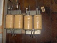
I need to do something with these monster trafos
Each 2x 38Vac, 2kw
I have had them fore too long, and payed serious money some years ago
I think its due time to put them tp work, or sell them
Considering that this amp doesnt need more heatsink, its possible to avoid a monster build, despite the huge trafos, and believe me, they really are big and heavy, just one of them will hurt to carry
Well, I know how much output I can expect with a normal SS amp, about 150watt I guess
But can I expect more output from a classD amp, due to the high efficiency 😕
And if bridged, can I still expect it to be 2ohm stable, due to the lower supply rails(50-55Vdc) ?
well, alone the cost of needed caps could buy me good switch modes
Attachments
Last edited:
And if bridged, can I still expect it to be 2ohm stable, due to the lower supply rails(50-55Vdc) ?
Oh, I see, the 300watt are rated in 4ohm, so its still a 150watt in 8ohm
So, my trafos giving up to 55Vdc is just above max
Hmm😱
5th, that sounds like a lot of work for seven days to see what it is really capable of? As described by you it sounds perfectly ordinary in stock dress. It takes more than seven days for the ear to tune into that too, and perhaps that's another reason.
Well any of the mods in the list I came up with are simply ideas of what one could do. I haven't purchased a ClassD module.
Instead of the OPA1632s, I've used 4 normal opamps to provide a 4th order highpass at 20hz. One to buffer the incoming signal, two to perform the filtering and one to invert the signal. I've also powered them with +-12V rails.
If I were to use the amplifiers for the entire system I'd need 6 more mono modules. But if I were to do that I'd most certainly power the input opamps with Super regs and possibly have a seperate regulator just for the 12V side of the TAS5630.
Although there isn't a lot to be gained by using the amps in PBTL mode over BTL unless you've got a really stubborn load. The voltage swing capable in each configuration is exactly the same, you just double the current capability going from BTL to PBTL.
As it stands I'm using LM317/337 for the 12V line and for my application that's more then good enough.
If you want subjective opinions on the sound of the ClassD unit you're better off reading what other people have said. Having said that mine, with the crappy output inductors, sound pretty darned good and are very easy to enjoy.
Regarding acclimatisation to the new sound, I don't think this takes any longer then an hour at most. If any part of the system is doing something that could annoy you, you'll be noticing it. And on the flip side if it sounds great you'll notice that pretty darned quickly too.
Any modifications beyond the stock unit would most likely result in subtle, but worthwhile, improvements. If you don't like the sound of the stock unit, you'll know pretty quickly and should just return it. If you like the sound and like modding, you'll probably enjoy trying to extract the most out of it that you can. Any modifications however would make it impossible to return the amp to ClassD.
Oh, I see, the 300watt are rated in 4ohm, so its still a 150watt in 8ohm
So, my trafos giving up to 55Vdc is just above max
Hmm😱
Each TAS5630 chip comes with 4 single ended outputs.
BTL mode ties two of these together, bridged, and gives you 150 watts @ 8 ohm @ 50V. This also gives you 300 watts @ 4 ohms.
PBTL mode ties all 4 channels together, giving the same 150 and 300 watts into 8 and 4 ohms. But now also gives you the capability to double that once more, to 600 watts into 2 ohms.
With regards to the power supply, the absolute maximum the chips can handle is quoted at 69 volts (with an absolute operating maximum of 52.5V). It might be worth contacting TI and asking them about it. The rails in a linear PSU will sag when under heavy load and as a result will limit the absolute maximum power the amp can deliver. It would make sense to have the rails slightly higher then 50V when the amp is idling for that very reason, but that's only if it wont explode.
So has anyone run these at a really high spl with some inefficient speakers? I am thinking about building a 2 channel version of one of these amps for my two fronts in my hometheater.
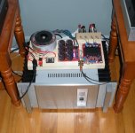
I just received my 300W x 2 kit the other day, and am putting it together now.
I should be able to test it out in the next day or 2.
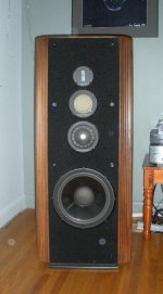
I have a pair of Infinity Kappa 8s I will try it out on, they are power hungry units and can produce impedance loads a fair bit below 4 ohms.
Should be a good test for it.
I should be able to test it out in the next day or 2.
I have a pair of Infinity Kappa 8s I will try it out on, they are power hungry units and can produce impedance loads a fair bit below 4 ohms.
Should be a good test for it.
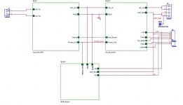
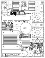
600w smps for tas5630
Ti engineer give me smps module schematic,now I make it reality,pic upload next time,i upload schematic here.
Design Name:SMPS For TAS5630
Design Engineer:by UpCotech, drawn by Kim N Madsen
Configuration:
UCC28061, UCC25600,UCC28600, INA210, TMP300,TL431
Setup:
50V max 600W, 1200W peak +/-15V 200mA
Ti engineer give me smps module schematic,now I make it reality,pic upload next time,i upload schematic here.
Design Name:SMPS For TAS5630
Design Engineer:by UpCotech, drawn by Kim N Madsen
Configuration:
UCC28061, UCC25600,UCC28600, INA210, TMP300,TL431
Setup:
50V max 600W, 1200W peak +/-15V 200mA
Attachments

Last edited:
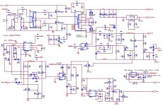
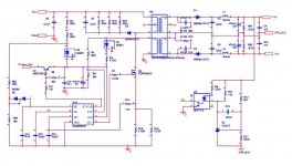
smps for tas5630
This guide documents a low-profile power supply that is suitable for AVR amplifiers or other high power amplifier applications. The power supply accepts a universal AC line-input voltage (85 VRMS to 265 VRMS), and produces an output voltage of 50VDC for loads up to 12 A (600 W).
The power supply is dedicated the Audio application and more specific the TAS5630/TAS5631 from Texas Instruments. The big difference compared to an industrial grade power supply is the typical user pattern of an audio-system. First of all, music is very dynamic with a crest factor typical in the range of 1/10 to 1/5 (Highly compressed music). Secondly, the user pattern of a normal audio system, it is running most of its time in low power mode (<5W) playing"background" music. It should also be noted, that an audio amplifier capable of delivering "x"-watts of RMS power with a reasonable audio performance (< 1% THD) is actually delivering a time varying power between 0W and 2 times the RMS power.
All this has been taken into account when designing the SMPS for the TAS5630
In the following the system features and functionalities will be explained and in the case where the normal procedures regarding power supply design has been modified to accommodate the audio-application, this will indicated.
The requirements for a modern AVR include a slim physical profile and the ability to operate from the ac-line input at close to unity power factor. Therefore a AVR application demands an power supply be of low height, and comply with the power quality requirements defined in the IEC standard, 61000-3-2. In addition, the combination of a tight physical package and the desire to meet Energy Star guidelines requires that the design also demonstrates very high efficiency. Described herein is a practical design that uses standard components. It achieves the requirements using a traditional two-stage power converter topology along with state-of-the-art power circuit control methods. The first stage is an interleaved, transition-mode, power factor correcting (PFC) boost pre-regulator. This is followed by an isolated LLC series resonant DC-DC main converter.
The design takes advantage of three integrated circuit (IC) power controllers. The PFC pre-regulator stage is controlled by the UCC28061, a dual-phase, interleaved, transition-mode PFC controller. The resonant LLC converter uses the UCC25600; a low-cost 8-pin controller. The third IC is the UCC28600. This is used to control a small 6-W flyback converter that provides a bias supply voltage.
I finally got a chance to test the amp with the Infinity Kappa 8s.
Although it is a powerful little amp, the 8s are just a little too much for it.
Heavy and low frequency bass passages can send the amp into protection mode.
That is not really surprising though, the 8s and 9s were known as amp killers back in the 90s as they can easily dip down into the 2 ohm and under impedance range. Most integrated amps and receivers back then just wouldn't cut it with these power hungry units.
The track "End Credits" for the soundtrack from Apollo 13 immediately shut down the amp several times, even at medium listen levels, but to be fair that particular track has a very wide dynamic range.
The track "Lets Groove Tonight" by Earth Wind And Fire would also shut down the amp on bass passages when played at medium/high levels.
Each time the amp did trip, switching it to standby mode and then turning back on reset it with no issues. A low frequency cutoff adjustment on the preamp would go a long way to making this amp work with speakers such as these.
I found the midrange performance to be good, but the upper end is a bit off with some slurring of s's and does become fatiguing at higher sound levels.
I have to admit though, I was impressed on how well it does sound out-of-the-box, especially considering the low cost. I know from personal experience that most equipment responds very well to tweaks such as bypass caps, power supply upgrades etc, so I consider this to be a diamond in the rough. Even after several hours of running at normal/medium listening levels, it barely gets warm. I am very happy with it, and looking forward to seeing what kind of improvements I can get out of it.
Btw, checkout the bread-board design, 2 x 8 spruce to be exact 🙂
Attachments
- Status
- Not open for further replies.
- Home
- Amplifiers
- Class D
- Class D Audio, Who are these guys?