Hi Cristi,
I have 8950th with 6800 uF, and I might experience pumping (sounds like a helicopter), and I have some some low distortion, as described earlier. The distortion is independent of the source, but only appears with signal. Also the distortion is independent of volume.
What can be wrong? Is the caps to small for my 2x24 volt transformer?
Just a remark to my above question:
This is from TDS8950th datasheet
"The noise generated by the internal oscillator is supply voltage dependent. An external
low-noise oscillator is recommended for low-noise applications running at high supply
voltages."
Could this be my problem? I don't know how internal oscillator noise sounds. I don't have a transformer with lower voltage to try this out.
if both channels of the amplifier are driven with signal in-phase, or just connected together, the bus pumping should not be significant since the signal is already inverted on the left channel. you should try to increase the capacitors value by adding extra capacitance to avoid umping, and to increase the zobel network capacitor value to avoid oscillation. the external synchronization is recommended when there are few amplifiers working together to avoid beating. for this, an external clock generator with 50% duty cycle and frequency in range og 600-720 KHz should be used. anyway, the problem is likely to be a GND loop or output to input parasitic coupling which create unwanted feedback.
I'm planning a new housing for my amps, and will first implent a new layout for the signal/power. I would rather not solder on the board. NXP actually recommends a better oscillator for high supply voltages, see my quote from the datasheet.
Hello Cristi
I am not shure of the layout of the connectors of the TDA 8920 v1.0 board.
Could you confirm I got it right ?
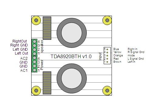
Thanks Cristi. I have a couple more drawings. Its done in OpenOffice. When I am done, I'll post the jpg here and send the source to you for reuse. I prefer a graph or a drawing rather than text 🙂The connections as you drawn are correct. keep in mind that the left channel output must be connected inverted, the loudspeaker will be connected with + at left GND and - at Left Out. this because the left channel input signal is applied to the inverted input of the ic, and the right channel signal is applied to the noninverted input. there are advantages of this type of connection such as the bus-pumping cancellation and easy BTL connection.
congratulations for the nice drawing, btw 🙂
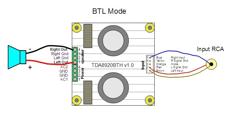
I build a mono BTL, single way (its a mono amp)
two more questions :
1. I want to avoid ground loops. I noticed that input Gnd pins 2 and 4 are connected via the pcb. I would cable only one.
Is this below cabling correct ?
2. power cabling.
Power Gnd pins 2 and 3 are connected via the 8920 pcb. I'll only cable one to avoid ground loop.
I have the SMPS250. Can I simply connect SMPS Vout+ and Vout- to TDA8920 AC1 and AC2 as shown ont the drawing below, eventhough its DC and not AC ?
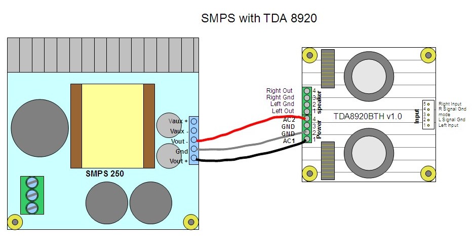
thanks again for your help.
I'm planning a new housing for my amps, and will first implent a new layout for the signal/power. I would rather not solder on the board. NXP actually recommends a better oscillator for high supply voltages, see my quote from the datasheet.
you should try to synchronize the amplifiers if you want to make a multichannel system, and could also can modify to use the inputs in balanced mode instead of unbalanced.
alkasar, the schematics looks fine, but yo should invert the loudspeaker terminals, the left channel is inverted, so there should be - and right is not inverted, so +. also, the smps output voltage should be set for lower voltage than the default +-30V, i recommend +-25V.
will do. Thanks.alkasar, the schematics looks fine, but yo should invert the loudspeaker terminals, the left channel is inverted, so there should be - and right is not inverted, so +. also, the smps output voltage should be set for lower voltage than the default +-30V, i recommend +-25V.
Cristi; Have not been able to access data on the integrated 8920 amp/ PS mentioned in post#28. Please help.
Thanks,
Pete
Thanks,
Pete
Hi Cristi,
I have 8950th based amps from you, and I have mentioned in this thread, a high frequency noise on start up. The time the noise a present got longer and longer, so eventually I just kept them on. One night I heard one of the amps with continuous noise and I shut it of immediatly. The next morning I turned it on, but only with at low freq. noise and the speaker cone dragged in to the cabinet (constant DC).
I have 8950th based amps from you, and I have mentioned in this thread, a high frequency noise on start up. The time the noise a present got longer and longer, so eventually I just kept them on. One night I heard one of the amps with continuous noise and I shut it of immediatly. The next morning I turned it on, but only with at low freq. noise and the speaker cone dragged in to the cabinet (constant DC).
Peter,
i will solve the problem with the manual net days.
Brian,
the high frequency noise is most probably generated when there is a GND loop or a parasitic coupling between input and output. if the problem is not solved, is very possible that the zobel resistors will burn and this will lead to higher noise, and eventually the IC will enter in protection mode or even fail. if there is DC component present on the output, is possible that this just hapent. can you measure without loudspeakers connected what is the value of the voltage at the output, then, if is equal with the supply rail voltage, measure with a multimeter when the module is powered off the resistance between output and that power rail to identify if the ic is damaged or just latch when you power on due to abnormal voltages on the pins.
one important aspect: did you mounted all the screws on the pcb ? because only one of them is connected at GND on the board, for star connection, the one from the rectifier bridge. if is not connected, can generate this kind of problems also.
Crap - my bad. I have used 1 or 2 metal screws and the rest i platic, because the holes I made was slightly inaccurate, and the platic screws could bend a little.
The high frequency noise on start up is present with a battery powered CD player, I guess the onlyu possible error would be my platic screws? I will test the modules, but I have extra on stock so no worries.
Btw. the amps sounds amazing compared to my panasonic SA-XR50 (analog input). It was really not fun at all to reinstall the panny after e few weeks with the TDA8950 modules.
7-pin connector - how to connect ?
Hi !
I just received 2pcs TDA8920SMPS and 2pcs TDA892x Amp V2.
They ship with 7-pin connector cables - but I can't find any information on what pins are used for what ?
Regards, Bjorge
Hi !
I just received 2pcs TDA8920SMPS and 2pcs TDA892x Amp V2.
They ship with 7-pin connector cables - but I can't find any information on what pins are used for what ?
Regards, Bjorge
Please check the pinout in the manual on the product page: Connexelectronic
here is the direct link to the amplifier manual: http://www.connexelectronic.com/documents/TDA89x0SMPS_Audio_Amplifier_Module.pdf
here is the direct link to the amplifier manual: http://www.connexelectronic.com/documents/TDA89x0SMPS_Audio_Amplifier_Module.pdf
I'm very sorry, the file is damaged when I try to open it !
It works fine for me... 🙄
Hi,
Im going to mount my board to the chasis but i would like to clear something first:
1. Do i need to put metallic screws into ALL the mounting holes, into the heatsink?
2. Is it ok that the "chip" have direct connection to the heatsink, or do i need to put some of the plastic in between so the heat is transfered, but there is no electrical contact?
3. My heatsink i mounted in my computer, is it ok that the heatsink have "electrical contact" with the chasis, or do i need to "seperate it with e.g. plasic screws?
EDIT: its the 8950th chip
Best Regards
Thomas
Last edited:
I forgot to mention that i have mounted both modules on the same heatsink, do i need to seperate them, so they cant see each other electricaly?
Metal screws in all holes are important, I've been told. Chip definately have to be isolated from the heatsink. Two boards either need two power supplies or share an external clock.
See also page 5 here
http://www.connexelectronic.com/documents/TDA892x_Audio_Amplifier_Module.pdf
See also page 5 here
http://www.connexelectronic.com/documents/TDA892x_Audio_Amplifier_Module.pdf
Last edited:
- Home
- More Vendors...
- Connexelectronic
- Class D Audio Amplifiers