Hello Workhorse,
Care to share you're experience regarding "using the input opamp as current limiter rather than integrator" ?
regards,
Savu
Care to share you're experience regarding "using the input opamp as current limiter rather than integrator" ?
regards,
Savu
Hello Workhorse,
Care to share you're experience regarding "using the input opamp as current limiter rather than integrator" ?
regards,
Savu
The opamp actually is transconductance amplifier which can be made functional to alter the gain of input stage with respect to current sense parameters set by the design.
hello everyone,
i have some time since i started considering building a class D amp but i was(and still am) a bit afraid of the complexity and unknown territory i'm about to deal with.
therefore, even if i've read a lot of information i'm still not sure about everything.
attached is a schematic adapted for my needs. is everything ok?
i'm not sure about the feedback resistor, as i saw in most of the schematics a filter with a 150pf cap for parasitics filtering. is that absolutely needed? what are the benefits? in the schematics from the datasheet i see 47k/3k3= 14db gain - is this correct? seems a bit too less.
do i need to lower a bit the gate resistors when using irfb4227? is 10ohm an optimal value?
😕😕😕
i need some help here. it would be much appreciated 🙂 (and sorry if i sound a bit stressing)
mag, what is the gain of your schematic?
PS if the schematic turns out to be ok, the next thing is designing a board. that should be fun 😎
attached is a schematic adapted for my needs. is everything ok?
No attachment.
i see 47k/3k3= 14db gain - is this correct?
No, 47k/3k3 is not 14 dB, but 23 dB. Do you know what decibel is? (However you wrote db, which means pcs - pieces - in Hungarian, but nothing in English as I know.)

i meant voltage gain (that's how the gain of an audio amplifier is usually expressed, right?). in the functional description of irs2092 they say Gv=Rfb/Rin, which is also some basic stuff i already knew.No attachment.
No, 47k/3k3 is not 14 dB, but 23 dB. Do you know what decibel is? (However you wrote db, which means pcs - pieces - in Hungarian, but nothing in English as I know.)
Hi!
I'm going to make my first D-class amp. Let say it will just run the subwoofer. Is it worth to reduce the freqency? I guess it would be easier to begin with D class.
I'm going to make my first D-class amp. Let say it will just run the subwoofer. Is it worth to reduce the freqency? I guess it would be easier to begin with D class.
@ papyrealoaded
Driving an IRFB4227 directly with the IRS2092 is not the best thing to do. It can be done but it my cause problems since it has big gate capacitance of the transistor. Buffers are recommended (ZXGD3002E6 or something similar).
Layout is crucial. you will need to design the PCB with very short traces, ground plane and very good decoupling of the chip and the power MosFets.
pointers:
Csd -1uF/10V (tantalum cap)
Cvcc - 47uF/25V (tantalum cap) + 100nF X7R (ceramic cap) in parallel
Cvb - 22uF/25V (tantalum cap) + 100nF X7R (ceramic cap) in parallel
Cvss, vaa - 10uF/10V (tantalum cap) + 100nF X7R (ceramic cap) in parallel
Cout (C in the output LC filter) - 1uF/250V (mylar or ceramic cap)
Lose the 7805 and 7905 and use dropper resistors and 5.1V zener diodes (dropper resistors have to be 1W minimum and NOT wound)
Use 1% tolerance resistors in the feedback circuitry
Use 1uF/100V (ceramic cap) from the drain of the upper mosfet to GND (decoupling reasons)
Use 1uF/100V (ceramic cap) from the source of the lower mosfet to the GND (decoupling reasons)
Use 2.2uF/250V (ceramic or mylar cap) from the drain of the upper mosfet to the source of the lower mosfet.
Use 1000uF/100V low esr cap from + to GND (connect as close as possible to the drain of the upper mosfet)
Use 1000uf/100V low esr cap from - to GND (connect as close as possible to the source of the lower mosfet)
Use T106-2 micrometals iron core (the red one) for building the output inductor or a ready made (ready wound) ferrite choke
Make power supply traces as short as possible
The traces from IRS to mosfet gates has to be as short as possible. Also avoid loops in this part of the circuitry
If you have ringing on the mosfets use RC snubbers in parallel with Drain and Source of the mosfet to damp the ring
Make the feedback circuitry as short as possible
If it all of this is respected you could reach 650khz sw frequency easily.
@ robivitez
The Sw freq has to be minimum 10 times larger then the max freq of the signal that you want to reproduce.
Regards,
Savu
Last edited:
Driving an IRFB4227 directly with the IRS2092 is not the best thing to do. It can be done but it my cause problems since it has big gate capacitance of the transistor. Buffers are recommended (ZXGD3002E6 or something similar).
Layout is crucial. you will need to design the PCB with very short traces, ground plane and very good decoupling of the chip and the power MosFets.
Regards,
Savu
I use a TC4420 to drive 2 pairs of irfb4227.
I drive one pair of irfb 4227 with just the 2092 but only run at 250KHz.
Hello Nigel.
250Khz is a decent sw freq (most kw level amps are running @ 250Khz)
But if the IC can do 800Khz why not aim for that?
Regards,
Savu
250Khz is a decent sw freq (most kw level amps are running @ 250Khz)
But if the IC can do 800Khz why not aim for that?
Regards,
Savu
Hello Nigel.
250Khz is a decent sw freq (most kw level amps are running @ 250Khz)
But if the IC can do 800Khz why not aim for that?
Regards,
Savu
I had problems with the 2092 and mosfets getting hot at those frequencies.
TC4420 has 55nS propagation delay.
ZXGD3002E6 has 2nS propagation delay.
In this case you need an emitter follower. ZXGD is the way to go.
If you were to make an opto isolated drive like for example with 6N137 followed by TC4420 than using TC4420 is a must.
Regards,
Savu
ZXGD3002E6 has 2nS propagation delay.
In this case you need an emitter follower. ZXGD is the way to go.
If you were to make an opto isolated drive like for example with 6N137 followed by TC4420 than using TC4420 is a must.
Regards,
Savu
If you use DirectFet types you could reach 800khz without melting the board.
But again 400khz is more than enough.
regards,
Savu
But again 400khz is more than enough.
regards,
Savu
TC4420 has matched 25nS rise and fall times.
The propogation delay isnt a problem as the rise and fall time are matched.
Your device as well as being faster is also cheaper by quite a bit.
The propogation delay isnt a problem as the rise and fall time are matched.
Your device as well as being faster is also cheaper by quite a bit.
I had never build amp with IRS2092 and I wanna try to bild with it but in data sheet nothing said about some stuff that I dont understand
All question are for schematic in post 1 of this treat
- I know for that fet death time must be 40-65ns ( resistors are like on schematic, gate res 10ohm and 8.2K+3.3K) for IRFB4227
- I know too that for VSS and VAA I need resitor (5.6V drop and 10mA and 5.6V zener)
*Now tell me, what is swich freq. with resitor 510ohms beetwen two 1n capacitors amd what is wit resitor 330ohms (without trim pot)?
*How can I set gain of whole amp
*How can I desiable curent sens and overload protection or how can I set uo it for diferent powers
*Can I use this schematic with different supplay voltage (from +-40 to +-90V) with all same values of components exept part for +12V ref to VCC- and VSS-VAA resistors
*How can I use SD pin for shut down funcion ( same like on IR2110 or ???)
You set deadtime using your scope to avoid masive shout throught and have the best audio quality possible.Without the scope set dead time so you will have no more than 150mA at +-45 vcc quiescent current.
You change gain and switching frequency by changing the 47 kohm and 901 ohm resistors..
Put CsD pin to ground for shutdown.
Try making datasheet schematic first and see how it works, i can not answer all your questions🙁...maybe someone who did make this amplifier will help you more .
.
You change gain and switching frequency by changing the 47 kohm and 901 ohm resistors..
Put CsD pin to ground for shutdown.
Try making datasheet schematic first and see how it works, i can not answer all your questions🙁...maybe someone who did make this amplifier will help you more
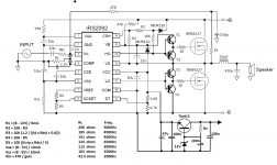
.I finsish schematic with lot of help of AN-1138
I attached you schematic. Can you look it and tell me is everuthing ok, with schematic andformulas...
But I stuck with calculation for R2 and R3, also with R4 and R5
On example +-70V @ 4 ohms load
IRFB4227 (Rds 0.024 max.)
AC sine voltage 48V before clip
AC sine current 14A (if speaker imedance fall to 3.5 ohms)
*that means aprox. 7A per voltage rail
-Dead time 45nS
- Rc = 120 ohms (Swich Freq. 300Khz)
- Rin = 47K / 30 = 1.5K (Gain 30x)
- Vaa = Vss = (70 - 5) / 10mA = 6.5K 2W
Now!!!!
- R3 = 10K (1.2 / ((Id x Rds) + 0.6))) = 10k (1.2 / (7A x 0.024) + 0.6))) = 15K
*How can I calculate R2 ???? R2+R3 have to be 10K (AN-1138)
- R5 = 10K ((Itrip x Rds) / 5) = 10K ((7A x 0.024) / 5) = 0.33K = 330ohms
* that means R4 = 9.2 K (this is maybe ok)
I dont know, I did all like in AN-1138
Where is my mestake??
And yes, which PNP NPN pairs can go to buffer?
Thanks
Attachments
- Status
- Not open for further replies.
- Home
- Amplifiers
- Class D
- Class-D Amp with IRS2092