Simulation library for IRS2092
Does any one know where I can get the Simulation library for IRS2092 and send to me?Thanks
Email:anshfe@hotmail.com
Does any one know where I can get the Simulation library for IRS2092 and send to me?Thanks
Email:anshfe@hotmail.com
About IRS2092 PWM Frequency
I prepare to build IRAUDAMP7S, but I have 3 questions about PWM Frequency:
Question 1: How to design IRS2092 work at 800 kHz PWM frequency? Have formula? Can work steadily for a long time?
Question 2: IRAUDAMP7S, May I change the output power MOSFET IRFI4019H-117P to IRF6775M? (No modify schematic)
Question 3: How to know IRS2092 work PWM frequency?
Could anyone tell me? Thanks!
IRAUDAMP7S
www.irf.com/technical-info/refdesigns/iraudamp7s.pdf
IRS2092 Datasheet
www.irf.com/product-info/datasheets/data/irs2092.pdf
IRFI4019H-117P
www.irf.com/product-info/datasheets/data/irfi4019h-117p.pdf
IRF6775M
www.irf.com/product-info/datasheets/data/irf6775mpbf.pdf
IIRC the chip is self resonant so that it depends on the way the integrator is designed. It is possible to synchronize it to a fixed frequency but the appnotes say this decreases the THD+N performance.
Self oscillation happens at the frequency where the loop crosses 180º phase shift. This phase shift comes both from output filter (if included in the loop), from additional frequency compensation and from propagation delay. The best way to get a first approach to frequency compensation values is simulation.
No models of IR2092 or output devices are required to do that (or even desirable).
The phase must not return to less than 180º above the intended scillation frequency. Also, phase must not cross 180º or get very close below that frequency. The slope at which phase approaches 180º below oscillation frequency also matters, it's one of the factors that determines frequency drop near the rails.
800Khz will require gate buffering, those little ICs already get stressed when driving just a pair of "not to heavy" MOSFET at lower frequencies. I don't like going that high in frequency due to increased switching losses, 400Khz is usually more than enough.
Changing output devices may require some adjustment of gate resistors and gate-source or drain-source RC snubbers, but this also depends on the parasitics of PCB layout and supply capacitors. You have to learn to model it yourself in a simulator, including all the parasitic inductances and capacitances that matter and that you will hardly find on any ready-made component model. Once you have close to optimum component values, you have to verify and tune it on a real prototype.
The "switching" simulation model has nothing to do with the model used for finding out frequency compensation. I usually model my circuits in several independent parts rather than trying to do it all together (which always causes trouble). In most cases, simple software like an old copy of Electronics workbench (bad as hell) is enough to obtain and tune the bode plots that matter.
no inductor?
it seems that there are no indutors in the +-45 supply.
400khz selfosc-frequency will make the SNR bad.😕
it seems that there are no indutors in the +-45 supply.
400khz selfosc-frequency will make the SNR bad.😕
Hello all,
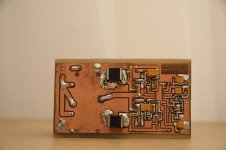
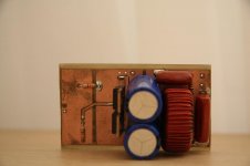
I have redesigned the pcb of this amp and built it.
Attached there are pictures with the almost complete work.
It is a bit smaller than an ipod nano 5th gen.
Powered at only +/- 20Vdc load a 4ohm small sub.
Fets used were IRFB5615.
I have encountered the following problems:
- the thing never started until i messed up with the low side over current voltage divider resistors.
- over current protection was almost always triggering when it was playing hard base.
- used about 3Vdc on the OCSET pin.
That means 3v*32mOHM = 96A. (hope i am right 🙂)
The thing is fried for the moment since i have shorted something because of my very tight PCB.
I am redesigning it to make it slightly bigger.
Please give me some pointers to where i have failed in making the over current protection work.
regards,
savu
Attachments
Hello all,
I have encountered the following problems:
- the thing never started until i messed up with the low side over current voltage divider resistors.
- over current protection was almost always triggering when it was playing hard base.
- used about 3Vdc on the OCSET pin.
That means 3v*32mOHM = 96A. (hope i am right 🙂)
savu
The over current protection looks at DS voltage to see if it is too high.
If your MOSFETs arent switching on fast enough this will cause the same problem. What value gate resistors are you using ?
My 2092 amp wouldnt power up and it turned out to be a glitch on the 12 volt rail which i cured with a 47uf capacitor on the vcc line.
The 2092 wont start up unless vaa, vss, vcc are correct with no glitches.
Then the 2092 will power down if the positive or negative DS voltages are out of range.
A wrong deadtime could also cause problems, I use 100ns currently on mine.
My only differences from the 2092 datasheet are 47uf vcc decoupler and i use IRFB4227 MOSFET's.
hello sir,
10ohm is the value of the gate resistors.
All the components are exactly as mag's schematic at the beginning of the thread.
the starting up problem was fixed but the over current protection always tripped.
regards,
savu
10ohm is the value of the gate resistors.
All the components are exactly as mag's schematic at the beginning of the thread.
the starting up problem was fixed but the over current protection always tripped.
regards,
savu
hello sir,
10ohm is the value of the gate resistors.
All the components are exactly as mag's schematic at the beginning of the thread.
the starting up problem was fixed but the over current protection always tripped.
regards,
savu
Are you clipping the amp ?
I believe it is designed to cut out if clipping starts.
I am not sure so look it up in the application notes.
I believe there is also a warning about vb dropping out if the amp clips and this will cause a reset.
Last edited:
Well ... to be honest i think i was clipping it.
It is hard for me to decide if that was clipping. I tested it with drum and base and dub step.
That kind of music has very profound and long base lines.
If the amp stops when it reaches clipping then that is what really happened.
But sincerely I am not so sure. I will finish the new PCB maybe next week and i will use the same component values.
regards,
savu
Well ... to be honest i think i was clipping it.
regards,
savu
Have you experimented with deadtimes ?
If you have too short a deadtime then you will get shoot through amd this will cause an over current event.
I use 100ns at the moment.
Hi Savu,
I had exaclty the same problems you are finding at the beginning:
1) the chip was not starting
2) OC protection tipping too early
1) It was due to a too low voltage on VAA / VSS supplies. In my original
desing I derivate the VAA/VSS from the +/-50V rails using R5 and R6.
On top of that the VAA/VSS rails supplies also a TL082 used as input
preamp. There was too much voltage drop across R5 and R6 and the
voltage pn VAA/VSS was too low. I fixed it by replacing R5/R6 with 2.2k.
If you are suppling with +/-20V check the value of those resistors, if you
are using 3.9k as in my original desing it is possible that it won't start or
that the voltage on VAA/VSS is just above the lower limit.
2) In fact there are 2 current sensing circuits: the low side and the high side.
The voltage on OCset is related only to the low side. If you have put
Vocset=3V you have set the low side current limit at 3V/Rdson=93.7A
which is more or less equivalent of disabling the protection. What about
the high side current limit? Resistors R9 and R7 set the high side current
limit. Check on the IRS20955 datasheet how to calcuate the values for
those resistors. On the IRS2092 datasheet nothing is explained.
In my design that is used in brigde mode with 4ohm load and +/-50V rails
the output power is around 900Wrms and my current limit is set at
something around 25A. Occasionally, when I am really pushing it too
hard, the current limit trips but for me is ok... it avoid to blow out my
subwoofer when I am pushing it too hard.
If your desing works only when the current limit is set at 90A there is for
sure something wrong. It can be a shoot-trough on the brigde or a too
high source inductance of your mosfets due to bad layout that creates
voltage spikes.
Check your dead time! My design works with 75ns dead time but I am
using IRFB4227 and not IRFB5615.
IRFB4227 IRFB5615
BVDss 200V 150V
Rdson 19.7mohm 32mohm
Qg 70nC 26nC
tr 20ns 23.1ns
tf 31ns 13.1ns
td_on 33ns 8.9ns
td_off 21ns 17.2ns
IRFB5615 is faster than IRFB4227 and its Qg is much smaller. On top of that
IRFB5615 as a very small turn on delay (8.9ns) and a turn off delay comparable with IRFB4227 (17.2ns vs. 21ns). This means that if 75ns dead
time is ok for IRFB4227 (with 10ohm gate resistor) it can be not enough for
IRFB5615 (one mosfet turn on when the other is not yet turned off creating
huge shoot-trough current because of the very fast td_on of the IRFB5615).
Increase your dead time at max and see what happens with a current limit set
at no more than 30A. Try also increasing the gate resistance, my design works fine with 10ohm but your mosfet are faster and Qg is much smaller. Maybe increasing Rg to something around 22-33ohm will be ok.
For the high side current limit I have used a slightly different configuration of R10, see attached schematics.
Other questions.
You tell that you have used my schematics but what about the output filter?
I see only one inductance (probably T106-2) but on my design I used a 4th
order Bessel type filter set at 35kHz on 2ohm load (due to BTL connection).
If you just copied the first part of my filter (22uH + 1.4uF) it is possible that
it is not right and your frequency response is peaking at high frequencies, please check.
Don't make it clipping. The IRS2092 is not too happy in this case. To avoid this I have set my current limit just before clipping. It is something I can do because I am using the amp only on one subwoofer , if I change the woofer
probalby the current limit needs to be re-adjusted.
Can you post your schematics, just to have a look. I am very happy that someone has tried to build this amp
ciao
-marco
Attachments
Hello Mag,
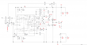
Here is what i did.
the amp is fried for the moment but i will redo the pcb to make it slightly bigger and in a week or two i wil start building it again.
Modifications apear in red on the attached schematic.
regards and thanks for the info
savu
Here is what i did.
the amp is fried for the moment but i will redo the pcb to make it slightly bigger and in a week or two i wil start building it again.
Modifications apear in red on the attached schematic.
regards and thanks for the info
savu
Attachments
Hello Marco,
I will makePCB for the amp in you're last posted schematic with after filter feedback and powered at +/- 70Vdc.
Do you have any pointers? loike for example after filter feedback parts values will change.
regards,
savu
I will makePCB for the amp in you're last posted schematic with after filter feedback and powered at +/- 70Vdc.
Do you have any pointers? loike for example after filter feedback parts values will change.
regards,
savu
Hi Savu,
I have never tried with post filter feedback, the values you find in the ¨
schematics are the calculated ones but never tried on a real board.
If you wont to try this please let me know your results.
The schematic I posted is powered at +/-35V where do you find +/-70V??
I have never tried to power up the IRS2092 with more than +/-60V. I have
an old post with a schematic powered at +/-85V but I have never finished it.
ciao
Hello Macro,
I want to power it with +/-70Vdc because irfb5615 can withstand max 150Vdc.
for this i have asked about some feedback.
regards,
savu
I want to power it with +/-70Vdc because irfb5615 can withstand max 150Vdc.
for this i have asked about some feedback.
regards,
savu
Hi savu,
if you go so high with supply voltage provide totem poles between the
outputs of the 2092 and the mosfet to help it drive them.
irfb5615 is rated 150V, with +/-70V you are really at the limit. Account that
some spikes can be present on mosfet drains that can pass 150V and put
your mosfet in breakdown.
It is better to change to irfb4227 (rated 200V) with such power rails and consider adding some RC snubbers on mosfets.
With such high rails you can theroretically get around 300W with 8ohm load
or 600W with 4ohm load. If you plan to drive a 4ohm load check you conduction losses in the mosfets.
I have never tried irs2092 at those high voltage and I can not tell you anything. Maybe there are other peoples who tried that
- Status
- Not open for further replies.
- Home
- Amplifiers
- Class D
- Class-D Amp with IRS2092