And therefore to get even low figure i have used the discrete modulator and comparator scheme using opamps to get 0.01% THD
Congratualtions for that choice.
Regards
Charles
Quasi-complementary fanatic? Have you done any mosfet amps like this using lateral fets (Hexfets)?
Reply
I have designed power amplifiers using N-CHANNEL IRFP250N MOSFETS in quazicomplementary manner
I have designed power amplifiers using N-CHANNEL IRFP250N MOSFETS in quazicomplementary manner
Yes, that's what I meant - a conventional amp with qcs. I've got lots of N-channel fets from SMPS's, even a number of 500v 32 amp ones and basically no P-channel ones. Gotta go now. Midnight again!
Did you ever have a look at this recent thread ?
http://www.diyaudio.com/forums/showthread.php?s=&threadid=25790
Regards
Charles
P.S. It isn't using the same type of FETs but should be reworkable.
http://www.diyaudio.com/forums/showthread.php?s=&threadid=25790
Regards
Charles
P.S. It isn't using the same type of FETs but should be reworkable.
Reply
i have designed quasicomplementary amps using n-channel mosfets upto 2KW in CLASS-AB mode
NOW what ur plan CIRCLOTRON
i have designed quasicomplementary amps using n-channel mosfets upto 2KW in CLASS-AB mode
NOW what ur plan CIRCLOTRON
Dear Amp Man,
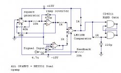
i'm sorry , but only one thing of the your circuit can be working - triangle generator, however at 60khz(isn't 250khz) and it have almost sinusoidal form because opamps too slow. Your feedback is positive (only regarding upper fet, lower fet is always ON and with 60khz frequency it's OFF for 300nS ), input R=1K & C=4.7U gives -11db at 10hz, however your circuit with lm3524 has much more errors. Why you write 0.01%, but not 0.0001%? Why are you stopped?
Man, just tell me - "smile, you in candid camera"
Best regards Ivan.

Reply
What will be the best ?
A Triangular Wave or SAWtooth wave to be used as modulating carrier?
What will be the best ?
A Triangular Wave or SAWtooth wave to be used as modulating carrier?
I would go for the triangular wave, as I think PWM conversion will be more linear due to less dU/dt in the reference signal.
hi.
>Dear Amp Man,
i'm sorry , but only one thing of the your circuit can be working - triangle generator, however at 60khz(isn't 250khz) .........Man, just tell me - "smile, you in candid camera">
hehe , i have suggested before to amp_man (or should i say amp_men....?) to build at least one of the amps before talking so much about how good it is 🙂
btw. some time ago you said you never heard about factor and his projects but the other day you said in emails it is actually your (late) brother , right?
are we all on candid camera here?
rgds karsten madsen - cadaudio.dk
Commentable Thoughts
Can this proposed schematic will give out of phase drive signal correctly??. I want to implement it because LM319 is dual comparator and therefore I want to use the full IC. and also i dont want to use CMOS ICs.
Comments,Suggestions,Insults,Remarks are most welcomed.
Regards
AmPmAn
Can this proposed schematic will give out of phase drive signal correctly??. I want to implement it because LM319 is dual comparator and therefore I want to use the full IC. and also i dont want to use CMOS ICs.
Comments,Suggestions,Insults,Remarks are most welcomed.
Regards
AmPmAn
Attachments
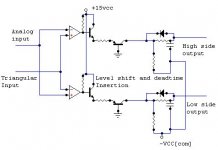
I thought that if the analog signal is triggered on two comparators that the distortion would be higher since they may not trigger at the same time.
Commentable Thoughts
But Sir, I have seen this type of implementation in several High-end Class-D amps.
Ampman requires more suggestions indeed.
Regards
AmPmAn
subwo1 said:I thought that if the analog signal is triggered on two comparators that the distortion would be higher since they may not trigger at the same time.
But Sir, I have seen this type of implementation in several High-end Class-D amps.
Ampman requires more suggestions indeed.
Regards
AmPmAn
I thought that if the analog signal is triggered on two comparators that the distortion would be higher since they may not trigger at the same time.
One can deliberately provoke this in order to achieve adjustable dead-time 😎
Regards
Charles
phase_accurate said:
One can deliberately provoke this in order to achieve adjustable dead-time 😎
Regards
Charles
Ampman ThanX SIR, PHASE_ACCURATE for his INVALUABLE suggestion . So, can i implement this circuit in my New CLass-D project.
With Sincere Regards
AmpMAN
- Status
- Not open for further replies.
- Home
- Amplifiers
- Class D
- Class-D Amp with Discrete Gate Drivers