Hello:
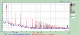
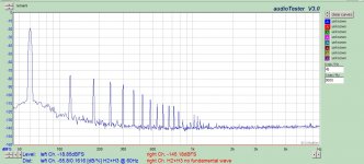
First post in the Class D forum, and first DIY project with a Class D amp. I can give a bunch of information if needed, but I have a fairly straightforward question. Inputting a clean sine wave into a PowerPhysics A-404 board. Input shown in blue.
Output is 24V into a 8.7 ohm resistive load, shown in red. I should note that the output is actually stepped up through a transformer into a 200 ohm load, but the amp is seeing a nominal 8 ohm load. The FFT is taken directly at the Class D output, not on the output of the transformer.
Any reason why the distortion has gone up a factor of 50?
Attachments
I don't have a good reason but have a few thoughts.
The magnetizing inductance of the transformer is adding a load in parallel with the resistive load reflected from the secondary. This will not be totally linear and will react with the output impedance to create distortion.
Does the distortion reduce linearly with level? There might be a threshold beyond which the distortion inceases rapidly with further increases in level which would indicate that that the tranformer is saturating.
The amplifier might be sensitive to the power supply ouput impedance.
Thanks for your reply.
I considered the nonlinear load caused by the transformer due to the B-H characteristic. To try and compensate, I made sure to run this 60 Hz transformer at 50% of its nominal voltage. Definitely not a saturated core. I would have expected this to be sufficient, since an amplifier is capable of driving a nonlinear loudspeaker load.
Regarding the above, no- distortion is generally unrelated to output voltage.
Power supply output impedance - good point. I am using a 150W switching supply, but I will try and add some extra capacitance on the 48VDC output to see if there is a difference. Will also look into adding the load at the amp instead of after the OPT.
If you have doubts whether the high distortions are related to the transformer load - simply load the amp without transformer directly into 8R and see if the results change.
I have only some semi randon thoughts.
Possibly the Class D or swithing supply high frequency noise is corrupting the signal source or confusing the Sound Card Analog to digital converter.
It might be worth investigating the high frequency noise generated by the Class D and the power supply and trying to reduce it.
Is the plot of the clean sine wave measured at the amplifier input with it driving the load?
Possibly the wiring arrangement is causing problems.
Has anyone else independently verified the distortion of a PowerPhysics A-404?
Last edited:
It is good that the distortions do not change much by the transformer load, but less good that the amp generally has high distortion.
Most dominant mechanisms for distortion in class D:
- Switching distortion, usually dominated by dead time distortion
- Modulator distortion caused by feedback
- Modulator distortion caused by a poor triangle generator (clocked only)
If you are suffering from dead time distortion you can see by comparing distortion at no load vs distortion at nominal load.
If you are suffering from modulator distortion you can see at the comparator input. Preferred shape of the carrier and/or carrier residuals is close to triangular.
Possibly the Class D or swithing supply high frequency noise is corrupting the signal source or confusing the Sound Card Analog to digital converter.
...good point...
@zigzag: Do you use a low pass filter to keep the carrier artefacts away from your sound card?
Interesting you should say this; during the development of the front-end signal source, I discovered the Class D amp would send bursts of energy into my phase locked loop LP filter, causing it to wobble in and out of phase lock. I had to put the circuit inside a shielded enclosure, now all is perfect. Also, note in the very first post that I was able to get a good FFT of the input signal, which was taken simultaneously with the loaded output. So worst case it would muck up ch. 2 but not ch. 1.Possibly the Class D or swithing supply high frequency noise is corrupting the signal source or confusing the Sound Card Analog to digital converter.
It appears the majority of noise is generated by the amp, not the power supply. Although the amp has its own output filter, I also used the leakage of the transformer and a 0.015uF film/foil capacitor on the transformer secondary to filter out that last bit of noise. Didn't want to add too much capacitive load, as this can make the amp run unstable. Other than these small steps, I wouldn't really know what to do without upsetting something.It might be worth investigating the high frequency noise generated by the Class D and the power supply and trying to reduce it.
Yes, definitely. There is a 0.01% sine wave feeding into the amp while driving loads from 50W to 100W. Same exact output distortion characteristic.Is the plot of the clean sine wave measured at the amplifier input with it driving the load?
Not to my knowledge, and if you aren't an OEM, the manufacturer has little interest in speaking with you. I had some email correspondence with the president, and it was short-lived.Has anyone else independently verified the distortion of a PowerPhysics A-404?
Yes, that is encouraging. I am considering throwing in my AB subwoofer amp just to prove everything else is proper and reasonable.It is good that the distortions do not change much by the transformer load, but less good that the amp generally has high distortion.
Apparently not. This would imply the output is inadequately filtered, relying on the additional assumed inductance of the loudspeaker. This is typical, but I do have a large leaky power transformer in series which I would think is sufficient. If not, I have two thoughts:Do you use a low pass filter to keep the carrier artefacts away from your sound card?
1. The very first post showed a simultaneous capture of the input and output, while driving load. Since the blue input is verified to be clean (same signal I get from the source when Class D is powered down) I think I have validated that my sound card is not suffering from some type of EMI issue generated by the amp or switching supply.
2. If the amplified output is indeed clean, but the sound card is incorrectly capturing carrier artifacts and reporting as harmonic distortion, I need to filter this signal. Can I do this passively? Is this some type of aliasing problem? I will say, by the scope the sine wave looks great, but it's not easy to detect 0.5% THD with the eye. What I have been using is a 'filter' consisting of an auxiliary split bobbin power transformer to isolate and scale down the output suitable for the sound card. Would this not be sufficient to keep the sound card happy? If not, I wonder if I want this carrier-ridden signal driving my sensitive load.
Thanks for your knowledge base; I admit I have limited experience with Class D, but I do have enough equipment to troubleshoot and enough analog understanding to be dangerous and creative.
So I confirmed that I was able to change the DC power supply from 37V to 50V with no discernible change in FFT spectrum. Also was able to change input source such that output into 9 ohms changed from 20V to 28V rms with no change in FFT (DC set to 48V).
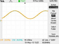
Attached a few pictures of the output; one is both output pins simultaneously. Looks reasonable; I would think the DC offset is normal due to PWM+filter action.
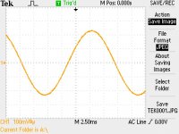
Second picture is output at split bobbin isolation signal transformer.
If this is not a filtering issue, it must just be a junk amplifier ?
Attached a few pictures of the output; one is both output pins simultaneously. Looks reasonable; I would think the DC offset is normal due to PWM+filter action.
Second picture is output at split bobbin isolation signal transformer.
If this is not a filtering issue, it must just be a junk amplifier ?
Attachments
Thanks for all the clarifications. The PowerPhysics web site isn't entirely convincing.
Junk amplifier is a bit strong. 0.3 % Harmonic Distortion may be considered good for a bass unit so the power amplifier might be adequate, just not great. It's also better than the approx 2 W integrated Class D amplifier from NXP that I measured last year.
Junk amplifier is a bit strong. 0.3 % Harmonic Distortion may be considered good for a bass unit so the power amplifier might be adequate, just not great. It's also better than the approx 2 W integrated Class D amplifier from NXP that I measured last year.
Well, data sheet claims max 0.08% THD from 10Hz to 20kHz, 100mW-400W. So we definitely do not meet spec. I would have been satisfied with 0.1%. Maybe I'll deal with it for now and upgrade to a different module when a good deal rolls around.
Maybe this module of yours is defective and faulty ? Does it also sound bad if you play music on it ?
What I have been using is a 'filter' consisting of an auxiliary split bobbin power transformer to isolate and scale down the output suitable for the sound card. Would this not be sufficient to keep the sound card happy?
Passive filters are great. I am typically using between 2nd...4th order. Simple sequenced RC filters, always stepping up the impedance about factor 3.
You are using a normal power transformer for the THD measurement?
Likely this will filter out the mutiple hundrets of kHz carrier.
...but, you cannot easily rely on low distortion.
0.5% might be poor for a high quality amp. But IMHO it's not poor for a power transformer - also not when running at half voltage.
It is definitely possible that the transformer would be the weak link.
... have enough equipment to troubleshoot and enough analog understanding to be dangerous and creative.
Perfect starting point, like me some years ago. 😉
P.S.
I am wondering about your first screen shot of both outputs.
You mean + output and - output, right?
...would expect them in antiphase...
P.P.S.
Are you good in OP amp circuits?
Maybe this module of yours is defective and faulty ? Does it also sound bad if you play music on it ?
Don't know- it is strictly being used to generate clean AC for powering my directly heated triodes. In that sense, I am not concerned about how music sounds, but I understand your basic question of 'does it work'.
that was my assumption, and why I used the method.You are using a normal power transformer for the THD measurement?
Likely this will filter out the mutiple hundrets of kHz carrier.
...but, you cannot easily rely on low distortion.
0.5% might be poor for a high quality amp. But IMHO it's not poor for a power transformer - also not when running at half voltage.
It is definitely possible that the transformer would be the weak link.
Good point. I also have quality audio transformers (such as Lundahl LL1620 or LL1689 amorphous core). I will put that in and repeat the tests - I KNOW for certain that iron carries distortion in the 0.003% range. From personal experience in the power industry, an iron core transformer does add a bit of distortion, but 0.5% is quite high. I will report back.
I am wondering about your first screen shot of both outputs.
You mean + output and - output, right?
...would expect them in antiphase...
I kind of thought the same thing, but didn't bother investigating. It's possible I had one channel inverted. I'll look into it.
No problem; I just don't have a breadboard; I get pcbs made up, so tend to design for two months and then build a final product. It was for that reason I was hoping for a passive solution. I can build RC low pass filters easy enough, but I suspect this isn't the overall problem anyway.Are you good in OP amp circuits?
Thanks again.
Using an audio output transformer definitely helped me understand where distortions were coming from. You are right, the transformer is the weak link, but there are a few places where distortion enters.
First, connected a resistive load to the amp and removed the step up xfmr, using the OPT for measurements. I didn't capture a shot of the FFT, but it was essentially identical to the source quality, around 0.01% give or take. So the amp is doing its job into a resistive load.
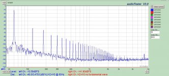
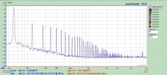
Then, I left the load as is, and just added the unloaded step up xfmr. The attached picture is the new result of the amp output. So clearly the amp does not like a nonlinear load. It is known that transformer excitation current consists of a great deal of 3rd harmonic, along with other odd harmonics in decreasing order. I was hoping keeping excitation would limit the current peaks, where the core gets closer to saturation, but definitely not enough. The amp does not prefer to push these nonlinear currents while maintaining a voltage sine wave.
Still thinking of how the even harmonics entered into the picture. Perhaps residual core flux?
First, connected a resistive load to the amp and removed the step up xfmr, using the OPT for measurements. I didn't capture a shot of the FFT, but it was essentially identical to the source quality, around 0.01% give or take. So the amp is doing its job into a resistive load.
Then, I left the load as is, and just added the unloaded step up xfmr. The attached picture is the new result of the amp output. So clearly the amp does not like a nonlinear load. It is known that transformer excitation current consists of a great deal of 3rd harmonic, along with other odd harmonics in decreasing order. I was hoping keeping excitation would limit the current peaks, where the core gets closer to saturation, but definitely not enough. The amp does not prefer to push these nonlinear currents while maintaining a voltage sine wave.
Still thinking of how the even harmonics entered into the picture. Perhaps residual core flux?
Attachments
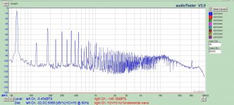
Next step was to reconnect load resistors to the output of the step up transformer, running around 65W. So this is measuring the 115V output. Knowing the distortion of the amp, I can now see the additional distortion of the transformer, which is significant. Not much more I can do about this unless some sense leads were available for the amp feedback.
Attachments
Thanks for the extra information which is interesting. My guess is that the amplifier doesn't like driving an inductive load even if it is linear.
A traditional linear amplifier is probably fairly tolerant of an iductive load. I guess that this is not necessarily so with Class D where the output stage is having to feed energy back into the supply with the switching devices carrying current in the reverse direction.
When I get back to measuring the NXP low power part and will measure the distortion with a speaker connected as well as with a resistive load just for interest because it's not high fidelity.
😎
..sort of a cool hunt for distortions
😎
And yes - vs your mains you have a nice improvement.
Do you hear the difference?
I am aware that some people like the sound of direct heated triodes with AC, but never heard complains regarding distortion of the mains. I guess most people are happy as soon as they manage to get the hum compensation right....
Enjoy your triodes!
- Status
- Not open for further replies.
- Home
- Amplifiers
- Class D
- Class D amp distortion causes