Mechanical ground loop is just that if the amp and source and mounted on the same surface and that surface is conductive and/or magnetic there could be a ground connection that way.
Maybe it's just radiated noise from the amp output. It is switch mode after all and it could interfere with or react with signal wires. Do you use shielded or twisted cables?
Also make sure that wires to ground from the amp and mp3 card are securely connected and use an appropriate thickness of cable.
I've had similar results as well where I simply had to resort to saying: "ok, these parts simply won't work together without separate supplies", and invested in an isolated ground supply just for the mp3 module. Or using a much smaller battery for that and a big one for the amp.
Hi Saturnus,
So far I've been using the "shielded" (STP I think?) cable from the amp and twisting it together with the unshielded one coming from the Source, I also tested with the "shielded" from both the amp and the source without results, the only thing I didn't try was using non-shielded cables on both sides (out of the source and to the amp), do you think that the shielding of the cables (which, being fair, can be defective) can be causing the issue and being the reason as to why not using the signal ground seems not to be making any difference, when, in fact, it should?
Because the truth is, using the ground loop isolator DOES fix the noise, it also removes all the low frequencies, but it does remove the noise...and, if "cutting" the signal ground doesn't fix it, Ground Loop Isolator shouldn't fix it aswell, right?
On the other hand, I did think about using a small 12v battery to power up the MP3 module but I couldn't come up with a design that would allow me to charge both batteries from a single "Mains" charger because, in my head, as soon as I connect both batteries to the Mains charger, Grounds will be connected and I'll have this stupid Ground Loop...Any idea of how I could come up with a "non-conflicting" design that uses sepparated batteries and a Single-Charger for both batteries?
Thanks
Ok... Let's review..
"So, what's the problem? Well, when I assembled everything for testing purposes, I connected the Amplifier to the Battery and the Audio Module to a 12v Transformer, spot-on, no noise at all no matter what function I was using (USB, Bluetooth, FM or Aux) BUT, when I connected both the Amplifier and the Audio module to the same power source (either to the Battery or to the 12v Transformer) Oh boy, what a mess."
This is basically the same issue I had..
"I modified a Lepai LP-808 by adding a 12 volt to 5 volt regulator for a Bluetooth receiver. It didn't work so well when I connected the rcvr. directly to the amp. (Both being powered from a common 12 volt battery) I installed an isolation transformer network between the Bluetooth and the amp input and it works fine.."
When Xarlitos used separate power supplies, all is good. When he combined both items to a common power supply.. Well.. 😉
I would suggest connecting back to separate supplies again to make sure that nothing is damaged and start from scratch..
Hi OffGridKindaGu,
I did that yesterday just for ease of consciousness, using sepparate power supplies works perfectly, independently if the Battery is powering the Amp and the Transformer the Source, and vice-versa, no problems with the individual items.
As soon as they are placed under the same power supply, "The Robot" comes to life...I'm seriously considering using a sepparate, small battery to feed the MP3 module as Saturnus said, but I'm having the issue with the charging system as I've described.
Now, starting from scratch, I made all the connections possible in all ways as far as standard connections allow me, the only thing that made any difference was the Ground Loop Isolator which also removed low frequencies (Note: With the signal ground disconnected, Ground Loop Isolator removes ALL audio).
Again, in the Audio Source, disconnecting one of the Grounds (Power or Signal) keeps the source running normally with the noise, both grounds disconnected shuts the unit down, I think this detail makes it obvious that the Signal Ground in fact does act as the Ground for the Unit when the power ground is disconnected, reason I don't understand why disconnecting the Signal Ground alone doesn't "break" the ground loop, as Saturnus said, it should, it really should...shouldn't it? :/
One thing I didn't try because my Soldering Iron broke and I can only afford one next month was putting some heavy wires feeding the amp and the source, right now the power wires for both units are the same (thin ones) and although with sepparate power supplies it doesn't seem to make a difference, maybe with a single power supply there is a big difference in the ground potentials causing this...Any way I can check this with a Multimeter? Maybe checking the voltage at the Ground of each unit? If a big difference is detected, is there a way to put both grounds at the same "level" so that current runs its normal path? (I read somewhere that 0.3V is already a big difference, correct?)
I'll only have time on Sunday to make further testing, thanks again for all your help.
As I wrote previously. I also had cases where there was a voltage differential. In one case an isolation transformer fixed it but in most it doesn't. Only an isolated ground supply or having separate supplied fixed it. In this case it should not be necessary though as the parts used are pretty much identical to ones I have tried.
The fault here is clearly not in the amp at all. There is something in the mp3 module that causes it. What exactly is difficult to say without having it in hand and start measuring but most of these cheap mp3 modules are really just barely worth the $2 price tag.
Hi again Saturnus,
The problem is in the MP3 module as you said, other "buyers" had the same issue and I've found one guy that said that breaking the AGND and GND connection on the unit and running it through a "throttle (inductor) would remove the digital noise.
Mr. Infinia was kind enough to guide me through what to do although I'm having some trouble following it, namely when he says:
"...determine which side is floating from power return..:"
"Use 10's of mH..."
"...from a line filter use a 1/2 side one winding only..."
Original post below.
"Originally Posted by infinia
yes I figured 'throttle' meant filter.
1st cut the connection A-D, with an ohm meter now determine which side is floating from power return (-), attach an inductor to that side to the battery( -). battery fuse removed of course
use 10's of mH? perhaps try a ferrite toroid* from a line filter use 1/2 side one winding only and connect other end to the battery ( -). warning measure voltages 1st to make sure gnd planes is equal to (-) at battery.
*you have access to a old junked ATX power supply it's the coil nearest connections to the AC input."
"Now, starting from scratch, I made all the connections possible in all ways as far as standard connections allow me, the only thing that made any difference was the Ground Loop Isolator which also removed low frequencies (Note: With the signal ground disconnected, Ground Loop Isolator removes ALL audio)."
I'd say that you're half way home. Now we need to figure out why the lows are disappearing.. 😉
A Google search on isolation transformer schematic will help you understand how it works and why you lose your audio when disconnecting the shield at either end..
https://www.google.com/search?q=gro...7JO2xsASEwYCQAw&ved=0CB4QsAQ&biw=1138&bih=543
Both input and output circuits become a separate circuit of their own. (L and R) Breaking the ground (Shield) at either end will disable the whole side. (Input or Output)
"Now, starting from scratch, I made all the connections possible in all ways as far as standard connections allow me, the only thing that made any difference was the Ground Loop Isolator which also removed low frequencies (Note: With the signal ground disconnected, Ground Loop Isolator removes ALL audio)."
I'd say that you're half way home. Now we need to figure out why the lows are disappearing.. 😉
A Google search on isolation transformer schematic will help you understand how it works and why you lose your audio when disconnecting the shield at either end..
https://www.google.com/search?q=gro...7JO2xsASEwYCQAw&ved=0CB4QsAQ&biw=1138&bih=543
Both input and output circuits become a separate circuit of their own. (L and R) Breaking the ground (Shield) at either end will disable the whole side. (Input or Output)
those 'ground breakers' thingys are they even magnetic, who knows? good line level isolating transformers are expensive for HiFi, the cheap ones don't do lows at a couple of volts, and most have rolled off highs. Maxwell equations says low frequencies without saturating the core need high number of turns. and at the upper end the cores eddy losses and winding proximity effects require advanced techniques.
I reckon they can save big $ by cutting the freq range to 60Hz -10KHz, should be good enough for most folks. 60Hz is bass for small speakers, so yer very smart in having OP check polarities.
Last edited:
I like this one. I bought 4 to avoid shipping costs. Really didn't notice any loss in fidelity..
Amazon.com: PAC SNI-1/3.5 3.5-mm Ground Loop Noise Isolator Works with iPod/Zune/iRiver and Others: Electronics
They "Claim"..
*Close to perfect response of +/- 0.03 dB from 2-20,000 Hz
*Utilizes proprietary audio transformers for a 1.3 dB gain
Cut the plugs off and 3 solder connections to each board. More simple than trying to connect 2 separate cables to a board..
^so funny, I thought bluetooth was invented to get rid of these wired do-hickys
I couldn't find a data sheet eg test conditions but some amazon users describe LF loss as well.
I couldn't find a data sheet eg test conditions but some amazon users describe LF loss as well.
^so funny, I thought bluetooth was invented to get rid of these wired do-hickys
I agree but the OP wants a single battery/P.S. to deal with. His source is more than just a Bluetooth unit..
I'm building a similar unit. (Bluetooth receiver, Amp, Speaker System) Portable, using one battery. I modified an amp (12 v.d.c.) by installing a 5 volt port to operate the Bluetooth receiver and connect to the amp via the 3.5 mm connection. (USB powered Bluetooth unit.. No internal battery)
It was my intention to use a common battery instead of messing around with 2 separate batteries, so I can relate. Of course, I had that nasty ground loop problem also and I was very disappointed. I cured it with an isolation unit but it increased the cost and took up room, which is limited..
I opted to go with a 5 volt bank battery to operate the Bluetooth unit and a lithium ion 12 volt battery to operate the amp. This actually opened another door, being I can move the Bluetooth receiver to another amp/speaker system and use it somewhere else with ease..
I purchased 5 volt 5600 mA. bank batteries for ~$4.50/Ea. This is cheaper than a quality isolation network and no worries about ground loop issues. The bank battery operates the Bluetooth receiver for as long as the 12 volt battery lasts and I can charge my MP3 player from the port that I installed in the amp if I choose. Worked out rather well, IMO..
Xarlitos Bluetooth unit is designed to operate at 12 v.d.c. so he doesn't have much choice than to resolve the ground loop issue or redesign the Bluetooth unit, by bypassing the 5 volt regulator on the main board and operate with another separate isolated output 5 volt supply or a bank battery. Perhaps an isolated 12v/12v buck supply buy they's pricy too..
IMO many class D amp are best served by using their differential inputs in combination with line level transformers, thereby bypassing grounds entirely, but that is more advanced than most DIYers can come to grips with.
I like this one. I bought 4 to avoid shipping costs. Really didn't notice any loss in fidelity..
Amazon.com: PAC SNI-1/3.5 3.5-mm Ground Loop Noise Isolator Works with iPod/Zune/iRiver and Others: Electronics
They "Claim"..
*Close to perfect response of +/- 0.03 dB from 2-20,000 Hz
*Utilizes proprietary audio transformers for a 1.3 dB gain
Cut the plugs off and 3 solder connections to each board. More simple than trying to connect 2 separate cables to a board..
Hi,
Didn't have time to do any testing this weekend as my Soldering Iron died (pretty old one, we had some good times together...), will try to purchase another one this month or, lacking funds, will borrow from a friend to do the testing quickly.
I have added the Isolator you mentioned to my Basket List, but given that I saw some comments regarding the loss of bass/low frequencies (problem I was having with the Isolator I was using), I want to try others things before going for an already tested solution with a different product. If all else fails, I'll try that before moving to a 2-sepparated-batteries alternative.
I have 1 thing in mind and I'd like your feedback in regards to it:
1.) The Audio Module requires very little Current to work (around 250mAh max I think), following the "Isolation Transformer" subject brought on earlier (not the Ground Loop Isolator), I found some Chips on ebay that supposely are DC-DC Isolated Converters - Isolated Power Supply Module DC DC 11 4 12 6V in to 12V Out Converter 4 Pins | eBay.
By assembling this chip between the power-source and the Audio module, would it act as an Isolated line therefore breaking the Ground-Loop? If it does, The input power of the module states "11.4v - 12.6v", batteries fully charged usually put out 14.xxV, any problems there that I should address or are those standard values?
Thanks
Hi
did you not pursue the D-GND disconnect methods I proposed?
1) disconnect A-D GND at that bridge, then at the open side, re-connect at the battery using a separate wire.
2) repeat 1) using a toroid inductor salvaged from an ATX PS supply.
be careful and check work twice eg your polarities, fuses
tip> mount inductor firmly and use small flying wires to reduce stress on the PCB connection.
Hi
did you not pursue the D-GND disconnect methods I proposed?
1) disconnect A-D GND at that bridge, then at the open side, re-connect at the battery using a separate wire.
2) repeat 1) using a toroid inductor salvaged from an ATX PS supply.
be careful and check work twice eg your polarities, fuses
tip> mount inductor firmly and use small flying wires to reduce stress on the PCB connection.
Hi infinia,
That alternative is my best bet (and, for the looks of it, my only hope) but when I was going to prepare things to test it on Saturday my Soldering Iron decided he didn't want to live anymore...Therefore I cannot break the connection between the Analog and Digital grounds and cannot tear apart the ATX, hopefully Wednesday I'll have my hands on a soldering iron for a couple of days so I'll jump into it.
I spent some hours "decoding" your explanation (don't get me wrong, I believe the explanation was straight and simple, but somehow "off" my modest electronics comprehension) but I think I did manage to understand what needs to be done, eitherway, I'll do everything except connecting to the battery, take 2 or 3 pictures of what I've done and post them here to check if I did everything correct (you'll have to trust on me regarding the polarity, just want to know if there wiring is according to what you instructed). If everything looks good, I'll cross my fingers and connect the battery.
As always, responsability for what is being done is 200% mine, if anything breaks/burns that's on me (wouldn't be the first time) so don't have any troubles in saying "do this, do that, that's ok to go" etc, I always dig a little for everything people point me to, so the final decision is always up to me (and on me).
Thanks again
Hi
sorry about my style of writing.
I think if you wire one side of the A-D GND "break point" direct to the battery (-) with a single wire you probably can neglect the throttle (inductor) solution.
this idea is 1) in my post above
most ground systems are based (-) but sometimes there are others, that's why I suggest polarity checks, but an ohm meter can be used to verify.
the inductor would be needed to connect the two GNDs back together for a local PCB solution but will stress those connections indeed.
Last edited:
Hi
sorry about my style of writing.
I think if you wire one side of the A-D GND "break point" direct to the battery (-) with a single wire you probably can neglect the throttle (inductor) solution.
this idea is 1) in my post above
most ground systems are based (-) but sometimes there are others, that's why I suggest polarity checks, but an ohm meter can be used to verify.
the inductor would be needed to connect the two GNDs back together for a local PCB solution but will stress those connections indeed.
Hi infinia,
No need to apologize at all, I'm the one that needs to step-up my game and learn, I'm asking for help here so I can't expect a "private teacher" to do the work for me, when "homework" is needed I just have to do it and enjoy the learning process.
If everything goes well, this is just the first of many DIY audio projects, the more I learn, the better my next project can be, can't appreciate enough all the help you guys have been giving.
Regarding the method we're discussing, I came across one thread regarding this specific Audio Module where some people were having problems with "frozen" units (it would turn on but wouldn't "do" anything, like if it was in Sleep mode) and the solution was connecting the AGND and DGNG, so my guess is that the original modules' AGND and DGNG were sepparated and for some reason they started "producing" them with a simple copper connection between A-D Grounds.
So, I'm not sure in which cases the unit wouldn't turn on but with some luck, maybe I don't need the inductor. If without the inductor I get a "frozen" unit, at least I know why lol
I'll post an update as soon as I get the Soldering Iron.
Regarding the DC-DC isolated converter, any idea if that's a good secondary solution or I'm totally confusing the "Isolated Transformer" subject?
Thanks
PS: Just in case you have any curiousity, I'm attaching the design of the "Radio" I'm building, it will be very simillar to the picture although the colours are not "quite there" (first one I'm making...)
Attachments
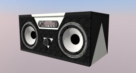
looks like a creative and fun radio, an auto sound DIN head unit would be less of a challenge I reckon. 😎
looks decent if it works as advertised w/o any other symptoms from introducing a new SMPS noise source! cant say for sure unless we know the mechanisms of the noise being introduced in the audio signal, but that could be another tool in the toolbox for "grounding" solutions. I like it because it regulates the DC output from battery input voltage wide range! ~10V-15V oops not quiteRegarding the DC-DC isolated converter, any idea if that's a good secondary solution or I'm totally confusing the "Isolated Transformer" subject?
Last edited:
Hi infinia,
After 1 month a lot of things happened, one of them being a "fried" IC (head-unit).
I bought another soldering iron (mine broke a few days before Mr. infinia came up with this solution) and after a "lot" of work desoldering that tiny connection between A-GND and GND (it is cheap chinese solder for sure) I connected the wrong GND directly to the battery and pufff, burned chip immediately. Not sure why, because I did test the circuits for continuity and checked which one was open, can only blame my enthusiasm for connecting the wrong GND I guess.
Now, a new Audio Module arrived after a few weeks and I will have time this weekend to give it another go. I will desolder again and test for continuity (this time writting on a piece of paper which GND is open) BUT, can you please confirm so that I don't screw this up (again):
1.) Place my positive wire of the multimeter on the + IN of the module (the one that will connect to the battery)
2.) Place the negative of the multimeter on A-GND and, on a separate reading, D-GND.
3.) The reading that shows 0 (zero) on the multimeter is the closed circuit, the reading that shows - (nothing) is the open circuit.
4.) On the GND that shows - (nothing), connect a wire directly to the battery - (minus).
5.) Connect both + & - IN of the module to the battery. If everything is good, it should work ok without frying anything.
Is that correct?
I also managed to desolder the inductor from the old ATX just in case I keep getting noise after doing the steps above, should I place this inductor between the "open" ground and the battery or between A-GND and D-GND?
Thanks.
Hi infinia and all,
So, I went Rambo (again) and pursued the solution explained by infinia without waiting for a reply, risking to burn the Audio module again but it had to be done 🙂
After reading more about testing continuity, I realized that my last test (the one that lead to burning the chip) was very, very wrongly done, which probably lead me to screwing up.
Right now I'm writing to you while listening to AC/DC on the audio system I just assembled, no noise, no blips, no bips, no nothing 😀 I still have a very small noise when nothing is playing but that's the amplifier's fault (nothing I can do there and it really doesn't bother me because the system will only be ON when it has music playing).
For anyone interested, here's how I did it (THANK YOU infinia).
I desoldered the connection between GND and AGND, then I tested for continuity. GND was continuum with the main GND, AGND was not, which means that any "fix" you are making, is on AGND.
Since I didn't want to burn anything again, I attached the amplifier to the Audio Module and tested for continuity. Amplifier GND and Audio Module AGND are continuum. This made me think that, well, nothing had to be done now, if the Audio Module AGND is directly connected to the Amplifier GND (that connects to the battery) I should have no problems.
And that was it, I crossed my fingers and connected the battery, POW, working without that "robot" talking out loud to me 🙂
I have no idea why the sellers of the Audio Module took the time to make the connection between AGND and GND, because clearly the "designer" of the circuit didn't want it to be connected and this Audio Module was specifically designed to work with an Amplifier, where the AGND was connected to the Ground via the Amplifier.
So, infinia, Thank you, you were the "light" in this path, and Saturnus, Thank you aswell, it was your super-positive statement saying that you worked with similar devices and that breaking the GROUND connection between the module and the amplifier would break the Ground Loop that made me think that something was clearly wrong here, something far wronger than a Ground Loop (I guess these were two Ground Loops combined in a very twisted way).
I didn't test connecting the AGND on the Module directly to the battery - (negative) since I believe this would create a Ground Loop?
And that's it, now I'll need to Work the wood and give life to the "Radio". Will post some pictures when it's done.
Thanks once again.
Hi, I have the same equipment and the exact same fail, but it is also solved by removing the solder from the two pads connecting AGND and GND 😀 thanks for the hint
hello can u plz take photo of the mp3 module and show where to desolder?
i have the same problem and it will help me alot !
thanks
i have the same problem and it will help me alot !
thanks
 to your success
- Status
- Not open for further replies.
- Home
- Amplifiers
- Class D
- Class-D Amp : Battery Powered : Head-Breaking Ground Loop