The Buffer is missing a 15k resistor from opamp's Inverting Input to Ground.
Hello Samuel Jayaraj. Thanks for your post. The Buffer as shown in the schematic has a gain of [1]. In a previous post, I used the missing 15K resistor as you mention above to give this Buffer a voltage gain of [2]. Eventually, a Buffer with voltage gain = 1, plus the added voltage gain from [PCF] is plenty for my hearing.
Best
Anton
Since I don't have the specified opamp, I am.thinking of experimenting with NE5532, LF353, OPA2064 for an H2 generator. Want to.compare the sound with J112 based H2 generator. Won't a buffered input stage with a level control, independent of an output stage with volume control, interspersed with an H2 generator be more versatile and prove as a universal preamp? Agreed that PCF is another matter. Thank you for your tireless and innovative contributions here.
On understanding the sound of vacuum tube power amps
Please go to post #490 in the H2 Thread by Mr. Pass. It contains a Class aP amplifier schematic, and it also explains the subject of this post. Thanks.
The attached schematic in this post is for a Class aP amplifier prototype; which mimics a vacuum tube [VT] power amp. It is mostly configured like the one I have already shown in the H2 thread; but with an important modification. This schematic uses a pair of SemiSouth SJDP120R085 [R085] instead of a pair of NPNs.
Mr. Pass has given me this pair of R085s during my experimentation with his DEF innovative circuit. Thanks again Mr. Pass.
R085 is a Depletion N-JFET. It mimics a vacuum tube [VT] pentode; because it has electical characteristics which resemble those for a VT pentode, and bias voltages.
Please note the value of Vgs [~-7 V] for R085. This value is inside the useful bias minimum voltage of [-10 V] for the drive OpAmp [1/2 OPA2134]. This minimum bias voltage is also applicable to Vg-k [grid-cathode].
The power output at the secondary of the power output transformer [OPT] drives the inputs of SONY MHC-1750; instead of Threshold S/150. SONY is a utility and a low-wattage stereo power amp [~10W/ch]. It finally drives a pair of ADS L730 loudspeakers.
Sound of this VT mimic.
Sounds great, detailed, and laid back. It has a subjective sound which I found different and better than I described for its NPN clone in the H2 thread. Its sound quality is fully commensurate with the finding of Mr. Pass in his articles which are entitled "H2 Harmonic Generator". He attributed this unique sound to H2 [second harmonic] negative phase or H2np.
The above is a valuable step to understanding VT power amps.
Best
Anton
Attachments
Last edited:
Hello.
I would like to know what do you think about using your tracking power supply with this amplifier NEW class A :Constant Current Push Pull amplifier with single SMPS and hybrid preamp
Or perhaps balanced choke loaded mosfet follower. (can you even aP a single supply design?)
I happen to have discovered a dislike for negative feedback form built up from semiconductors circuit after watching a movie about electricity and way how they scratched a mineral with needle reminds me of harsh feedback sound.
Ideally my setup would have a musical supply transformer too, but that seems pretty impossible for a civilian. So I am figuring to load it dynamically.
Thanks.
Hello VeightTripleDivision,
Thanks for your note. You ask valuable questions. I need more time to understand the schematic of Kokorian's Class A power amp. I also need to goto my older posts on the subject. I'll get back to you.
Best
Anton
Thanks for your note. You ask valuable questions. I need more time to understand the schematic of Kokorian's Class A power amp. I also need to goto my older posts on the subject. I'll get back to you.
Best
Anton
While you are in your process, I'll pinpoint some of the reasons I approximate to be true.
Conduction angle is all related to pre-history of atoms, it seems that wave theory and Einstein vs not-so-fully relative theories is now manifesting in every field of technical department.
Myself is forgiveful and accepts quantum tuneling as real thing. See it as class C amplifier's behaviour. Still, mind that you see far away galaxies in past. And One cannot "uninvent" history any further than in field of vision. Now a real master ear needs something inbetween - high effiency comes with "paraconductivity". High linearity comes with... whether being blindfolded by farawaygalaxies light rays, or by maximizing behaviour of aggresive leadership - superlowTHD design, fast, dynamic. At price of modern illness - tired of being awesome and busy conducting things noone can even see. Okay, electricity is awesome, mostly you can measure everything.
I myself prefer to live with +Oneness. Here is a scetch - pick big local mass object called inductor. Place it in perspective of TimeSpace Continuum. Determine -b[squared]+4ac two times. First one is your MC2, second one is inductors MC2. Transistor is +One. TimeSpace is minus. To be positive, all of a sudden all of present charges must be maintained /Realistic.
If you'll start to apply feedbacks, it will be like drinking to be socially cool, because drinking isn't cool, and everyone knows so and and and I must be the Chosen One, because I APPLIED "it" on "ME".
So /Really charged/discharged choke (ideally wound on planet's iron core (transformer / tracking PSU is an alternative route) gives you perfect Ear for observing perspectives also inside out. How do you pray for Transistor now? You see, a plus is a plus. Field effect or Germanium, each has it's angle. And behaviour. I find it hard to bias Hexfet without microphonic feedback. J-fet is my burning star. Si-BJT, well, behaviour of Si-BJT seems systematic, numberologic, often two-faced. Germanium OTOH is plain simple, yet never satisfied with one lucky spin. So spin the Si-BJT the most. Apply J-Fet patches where peace is to be preserved (like input buffer, analogue pickup or maybe DAC). Germanium is quite nice if you are. I use PNP emitter follower for extremely massive quantity and quality, somehow the complementary NPN device is driving it..crazy. Because junction submits energy. Now I must find a way to have a wise way to drive HexFet. It wants all fun, and elevated above it. Accessible right at hand. Must be the appetite grown by choke-plexus. One way would by by adapting the speed/effiency vs linearity @ power sharing with other same species / maybe different sex device counterplaying it's passivity. Other possibility might, perhaps be powertube OTL hybrid. That one comes with lots of steady heat though. Even clearly visible one, that has an expression of "I am glowing, yet quite blinded by surrounding currents. Can you open some quantum tunnel for me? Sure, circlotrone with heaters somewhere in equatation.
Okay, I have no valid schematics on hand for anything, just complaints about everything. I must be sent by Si'me Agints.
do they come with little umbrellas or pink elephants?
oohh wade a minute does it come in a paper wrapped rocket shape??
oohh wade a minute does it come in a paper wrapped rocket shape??
Black currant. For real, it's enzymes inhibitor. It means that your serotonine, dopamine and whatelse not get's longer spans of experience. I tend to settle on something and then any topic of importance is like a drug that (also never fully) consumates you. That way I am lead to existential conundrum and from there it is easy to find a way up to some smiles about things that impress me. Believe it or not, feedback used to impress me. Now I must let go. Still I would like to return once to integrate Faraday's and Maxwells equatations. It says that coordinate* is a perspective. Higher frequency, smaller size. There must be a lambda for capacitive feedback being fully capable for use in algorythm that I once dreamt of being realized digitally also in analogue technics. I imagine tons of external passive RLC interplaying semiconductors so they would cancel evenly. Of course all of it for basically One'ses Transistor.🙂
Hello.
Hello.
I would like to know what do you think about using your tracking power supply with this amplifier NEW class A :Constant Current Push Pull amplifier with single SMPS and hybrid preamp
Or perhaps balanced choke loaded mosfet follower. (can you even aP a single supply design?)
I happen to have discovered a dislike for negative feedback form built up from semiconductors circuit after watching a movie about electricity and way how they scratched a mineral with needle reminds me of harsh feedback sound.
Ideally my setup would have a musical supply transformer too, but that seems pretty impossible for a civilian. So I am figuring to load it dynamically.
Thanks.
Hello,
Please go to post #215. It shows a schematic of the tracking PSU and explains how its works. One obvious point is it does not charge capacitors. Charging caps defeats the tracking!
Best
Anton
While you are in your process, I'll pinpoint some of the reasons I approximate to be true. ..... complaints about everything. I must be sent by Si'me Agints.
"Is it not said, In the beginning was the Word and the Word was God? Did not all being begin with a bolt of lightning? It struck the sea and the sea conceived. All is charged. The words that tell of charge are themselves charged. The ampere is produced by one watt acting through one ohm and it is equal to one coulomb per second and its sign is I. And I-ampere is by interpretation God the Father, and watt is What the Ineffable, and coulomb is by interpretation Dove, which is to say the Holy Ghost, and ohm has the sound of homme, which is Man. In short, I saw that God is Electricity. And I said weeping, 'Why me, O Lord, why me?' But His will I will not resist."
Seven Day's Wonder, by Edward Wellen
The Magazine of Fantasy and Science Fiction, March 1963
Hello,
Please go to post #215. It shows a schematic of the tracking PSU and explains how its works. One obvious point is it does not charge capacitors. Charging caps defeats the tracking!
Best
Anton
Perhaps it does. I am just wondering if one can repurpose tracking PSU for applying square law bias for a simple class A amplifier, by increasing bias with increase of input signal, and keep the capacitors for something like delta sigma principle - using a differential opamp and comparator between P-Channel and N-Channel device so the active bias point would always be bound to nature of the transistor itself. It should always oppose it's current state, and always return in quality of harmony while amplifying. Life and Death instinct. The Capacitors should keep circuit inert in it's behaviour and speed up the diffraction movement of signal, therefore we see that "capacitor distortion" would ask us to dump more chromatic gamma currents (most likely not into speaker). There we don't force the signal to conquer opposing output, but rather use Lindley's paradox - Wikipedia by approximating the influence of ESR and decreasing the bias of FETs, while increasing PSU gain at rate that fits into loop of signal by reducing bias height (gate bias of amp), increasing PSU voltage gain and if necessery reducing input signal by shunting it with active device. Theoretically a feedback loop should never close, yet the signs of negative feedback also wouldn't be in place - the polarity of signal wouldn't be changing within the cycle of error deduction. Instead the delta volume of error would be proven, just like recording audio signal into capacitor and when you are "replaying it", it's recording's sequence is altered (atleast happened to me). While the Push/Pull differential/comparator is active, bias is falling and PSU voltage rising, the speaker output error part can be captured and recycled as spikes of it. As soon as the input signal is warned about error, there is nowhere to dump the memory of distortion, psu increase from stable opamp output / decrease of bias height leads to transient energy which we now use to stabilize condition and to regenerate faster than anything - the square law loophole, so it absorbs it and increases the bias again.
I think I will attempt to prove my sanity on capacitor here. Perhaps it's behaviour analyzed by a probe of it reaching for negative feedback point (but being denied) would be interesting to observe. Like a 3D brain scan.
Please show your proposed schematic of the power amp as you described in the first 4 lines of your post. Thanks.
Will take a while to reconstruct the image I got when I woke up in early morning and was going to work. If you care, I shall deliver eventually, when my spirit kicks in.
 is how it looks. Like a diamonds in cards. Current shall not exceed .... nor .... (I have strong dyslexia and ehhm, this awkwardness when I am not strong on topic).
Is square law about not exceeding yet delivering?
Does it forbid to simultaenously increase diagonal exponent?
If so, it is corelated within all laws I have seen. Except it cannot do magic thing with One(!!!) single Transistor.
I don't say I can. But I oppose this balanced technique with delta volume. Joules would understand.
Now leave me in peace, and I will practice electronics in mindspace called thinking.
is how it looks. Like a diamonds in cards. Current shall not exceed .... nor .... (I have strong dyslexia and ehhm, this awkwardness when I am not strong on topic).Is square law about not exceeding yet delivering?
Does it forbid to simultaenously increase diagonal exponent?
If so, it is corelated within all laws I have seen. Except it cannot do magic thing with One(!!!) single Transistor.
I don't say I can. But I oppose this balanced technique with delta volume. Joules would understand.
Now leave me in peace, and I will practice electronics in mindspace called thinking.
A current source amp using SJDP120R085 [R085]; Part1
[R085] is switched "hard" by analog pulses to generate the subject. This amp's schematic will follow.
I have a spec. sheet for [R085] by SemiSouth. I scanned several pages of it which I'll post individually because each is a large JPEG, and each has different info.
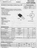
The attached scan is the front page [Part1]. The relevant performance of [R085] to this amp is shown in the Features section:
1. Extremely Fast Switching.. Analog pulses are much slower [rise/fall times] than square ones. Thus [R085] will perform well.
2. Rds (on) = 0.075 Ohms; close to a dead short which is a very welcome spec to pump high current levels thru the load.
3. Voltage Controlled with a low Gate Charge and Capacitance. These properties will not slow down the action of analog pulses. No slewing!
The breakdown Drain-Source voltage for [R085] equal to [1500 V] is truly impressive. But this prototype amp will use a high current 5-15 V SMPS as its PSU. I am using a 15 V PSU with an aim to go to 5 V.
This front page has many more important nuggets. Part 2 will follow.
Best
Anton
[R085] is switched "hard" by analog pulses to generate the subject. This amp's schematic will follow.
I have a spec. sheet for [R085] by SemiSouth. I scanned several pages of it which I'll post individually because each is a large JPEG, and each has different info.
The attached scan is the front page [Part1]. The relevant performance of [R085] to this amp is shown in the Features section:
1. Extremely Fast Switching.. Analog pulses are much slower [rise/fall times] than square ones. Thus [R085] will perform well.
2. Rds (on) = 0.075 Ohms; close to a dead short which is a very welcome spec to pump high current levels thru the load.
3. Voltage Controlled with a low Gate Charge and Capacitance. These properties will not slow down the action of analog pulses. No slewing!
The breakdown Drain-Source voltage for [R085] equal to [1500 V] is truly impressive. But this prototype amp will use a high current 5-15 V SMPS as its PSU. I am using a 15 V PSU with an aim to go to 5 V.
This front page has many more important nuggets. Part 2 will follow.
Best
Anton
Attachments
A current source amp using SJDP120R085 [R085]; Part 2
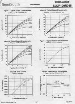
The left-side scan from the spec. sheet of [R085] shows a truly impressive current switching performance in each of Figures 1, 2 and 3. The prototype amp understudy aspires to get this performance; but..
Each Figure is a plot of drain current in Amps [Id =Y axis], versus Drain-Source Voltage [Vds; up to 5 V]; enabled by varying Gate-Source Voltage [Vgs]. Notable:
1. Special test equipment was used to generate these graphs. I am using a scope, pre-matching resistors and assessing its music's subjective performance.
2. The pulse width of the input signals which enable [e.g. 0 to 60 Amps!] is in nanoseconds. Used for proper operation and to safeguard [R085] from stepping outside its SOA and/or its peak junction temperature [Tj].
2a. The attached right-side scan shows Figure 14 which addresses thermal performance. Junction temperature; [Tj] per unit W generated therein is strongly affected by the pulse width of the switching input signal. Analog pulses have long pulse widths; between ~ [1. E-04 to 1.E-01] seconds. They are pulse-width and pulse-height modulated. They'll comparatively run [R085] a bit hot.
The above will help me make a respectable power amp. Its schematic will follow.
Best
Anton
Attachments

A simplified schematic of the current source amp using [R085]
Dr. Michael Mazzola [Semisouthfan] is a co-inventor of [R085]. Post #521 in the thread SemiSouth boiler room shows a picture of an [R085] device he crafted. It is a plug-in equivalent for 6L6 vacuum tube for use in the power output stage of a certain Fender amp. Its status is unknown to me.
I experimented with Dr. Mazzola's approach. It works. By example, please see post #245 in this thread which shows a typical circuit; albeit with a + 60 V [plate] or drain volatge.
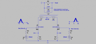
The attached simplified schematic is for the bench prototype. Please note the following which are different from the above:
1. Drain-Source voltage = 5 V; like in the spec. sheet of [R085]. I am using a regulated and linear 5V/2A PSU.
2. The windings of the output toroid power transformer are connected in reverse to that I practiced in post #245; meaning:
2a. The two low impedance Secondary windings [12 Vac] connect to the drains of [R085]. Power output [Vo] is taken across the primary windings which are connected in parallel.
2b. This approach enables [R085] to push a high level of drain current thru the [12 Vac] windings. As suggested in the spec. sheet.
3. Analog pulse signals are half-wave precision rectified music signals. They are 50% duty. By example; a 30 Hz. music cycle has a 33.3 milliseconds duration [0 to t1]. Each [R085] is ON for 16.7 milliseconds during its switching turn.
4. The source degeneration resistors [0.1 Ohm] are matched.
I'll post a full schematic.
Best
Anton
Dr. Michael Mazzola [Semisouthfan] is a co-inventor of [R085]. Post #521 in the thread SemiSouth boiler room shows a picture of an [R085] device he crafted. It is a plug-in equivalent for 6L6 vacuum tube for use in the power output stage of a certain Fender amp. Its status is unknown to me.
I experimented with Dr. Mazzola's approach. It works. By example, please see post #245 in this thread which shows a typical circuit; albeit with a + 60 V [plate] or drain volatge.
The attached simplified schematic is for the bench prototype. Please note the following which are different from the above:
1. Drain-Source voltage = 5 V; like in the spec. sheet of [R085]. I am using a regulated and linear 5V/2A PSU.
2. The windings of the output toroid power transformer are connected in reverse to that I practiced in post #245; meaning:
2a. The two low impedance Secondary windings [12 Vac] connect to the drains of [R085]. Power output [Vo] is taken across the primary windings which are connected in parallel.
2b. This approach enables [R085] to push a high level of drain current thru the [12 Vac] windings. As suggested in the spec. sheet.
3. Analog pulse signals are half-wave precision rectified music signals. They are 50% duty. By example; a 30 Hz. music cycle has a 33.3 milliseconds duration [0 to t1]. Each [R085] is ON for 16.7 milliseconds during its switching turn.
4. The source degeneration resistors [0.1 Ohm] are matched.
I'll post a full schematic.
Best
Anton
Attachments
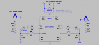
Current Source Amp using [R085]
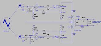
The attached is a detailed schematic of the prototype amp.
Post #200 in this thread shows the schematic and build of the precision rectifier generator; which provides analog pulses [Vin and Vin'] to the shown output stage.
Please note the following:
1. The two [R085s] need to idle equal source currents. I show a calculated [+18 mV] across the/each 0.1 Ohm source resistor. This biaing voltage is generated by using this equation: [15 V/820 K] X 1K. The 1 K resistor which is highlighted with a rectangle [or the other mirror] is minutely adjusted [+/-] to make the bias [source] voltages as close in value as possible; granted the source resistors are equal. Thus each [R085] idles at 1 W from [0.18 mV/0.1 Ohm] X 5 V.
2. This prototype has the propensity to generate +/-H2. This is a consequence of unequal [Vin, Vin'] and/or an inherent [unknown] system asymmetry. I reverse the loudspeaker leads periodically to assess the resulting H2. Both loudspeaker connections give a fully satisfactory and pleasing music.
3. In use, the output of the OpAmp moves the Gate Voltage of [R085] from [-6 V at idle] to more positive values; towards 0 V.
I was surprised this amp sounds great driving a hand-me-down 50 year old Karlson; which has a coaxial driver.
More to post.
Best
Anton
Attachments
- Home
- Amplifiers
- Pass Labs
- Class aP amplification