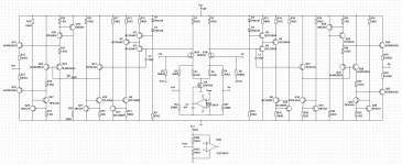
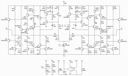
Well, now this is something very different. This is a differential folded-cascode stage with proper common-mode feedback. Actually, this is a dual-ended version of my RK-autobias-200W amplifier.
The CM feedback is exactly what I was describing in post 13.
Yes sir it is, the topology seems really interesting to me. Do you know of any source where I can learn more about it? Teachers dont have much time these days.


That open loop gain is not high enough to get benefit from feedback. You have enough feedback to create higher order harmonics, but not nearly enough to suppress them. Look at the article by Baxandall on page 54. https://worldradiohistory.com/UK/Wireless-World/70s/Wireless-World-1978-12.pdf Particularly Figure 7 on page 56. Feedback on 2nd harmonic distortion creates all the other orders of distortion, while reducing the 2nd harmonic. More feedback (ratio of open loop to closed loop gain) is needed to suppress these new harmonics, also. You only have 9dB of feedback.
A differential input followed by a differential pair is capable of much more open loop gain than 32.5 dB. 80dB of open loop gain is a better target. At least 66 dB. Active loads should be used in place of R1, R2, R15, and R18. Simply measure what is going through those resistors, and replace them with current sources with the same value current.
One of the main reference textbooks on amplifier design are Analysis and Design of Integrated Circuits, by Gray, Hurst, Lewis, and Meyer. Go look for it in a college library, or borrow it from one of your teachers. Another is Design of Analog CMOS Integrated Circuits by Behzad Razavi. It's all CMOS, of course. These are graduate level textbooks, but the math is all algebra.
What textbooks do you have now?
Do you know how to use your simulation tool to find distortion?
A differential input followed by a differential pair is capable of much more open loop gain than 32.5 dB
Correction: I meant to say a differential input followed by common-emitter VAS stages is capable of ...
A differential input followed by a differential pair is capable of much more open loop gain than 32.5 dB. 80dB of open loop gain is a better target. At least 66 dB. Active loads should be used in place of R1, R2, R15, and R18. Simply measure what is going through those resistors, and replace them with current sources with the same value current.
All noted Russel
Instead of R15 and R18 ill try a npn current source like in the rest of the circuit.
For R1 and R2 do you mean a current mirror or also current sources?
My teacher warned me that the DC servo can add a lot of distortion, this is why he thinks regular NFB is better opposed to CFB. I'm not sure if he had more reasons next to modularity.
I don't really agree with your teacher, here. Although the word "can" covers a lot of possibilities. The CM DC servo has virtually zero output at audio frequencies. If I take zero and divide it by your audio signal, I get zero.
If you do a dual-ended design, you have to have CMFB. The decision to make is whether that CMFB should be near DC only, or the same bandwidth as the NFB. I think you made the right choice with near DC.
All noted Russel
Instead of R15 and R18 ill try a npn current source like in the rest of the circuit.
For R1 and R2 do you mean a current mirror or also current sources?
You cannot use a mirror, because you need the output from both sides. So, yes, identical PNP current sources. in place of R1 and R2. The CMFB and NFB keep the operating points where they need to be.
I would not worry about this.
The human ear is actually almost completely insensitive to phase shift. Very few human ears can hear 20 kHz at all, and none can hear the phase shift at 20 kHz. Experiments were done with all pass filters that introduced phase shift in the midrange, but not amplitude change, and no one could hear it at all.
The cochlea in your ear is progressive filter (a spiral), with auditory nerve endings along the way. Each nerve ending senses a band of frequencies. The nerve senses if a frequency is present, but not its phase. The brain does a lot of post-processing on the incoming sound, but it's not fast enough to sort timing differences below about 15 ms.
15750hz is almost a tone but more of a "presence". That is the CRT oscillator
on old TV's .. BTW.
In music, the 14K + realm contains subtle parts of the soundfield. Most 21st century content nearly ingnores this.
young people seem ignorant of this reality. They seem to think I am DSP'ing
(or gaming) the music they know on a system that does HF well (CFA bjt).
But they DO like it. A "wow" is worth it.
OS
I remember being able to hear CRT TVs scream. And I remember when I quit being able to hear that. (Now, there are none left to hear.) If I can no longer hear those frequencies, do they still help me? I cannot say definitively no, but I doubt they do.
Young people, on the other hand...
You bring up an interesting idea. That 21st century audio content contains less energy above 14 kHz. It's certainly true that 21st century audio contains no energy above 20 kHz, because of digital brick-wall filters. (some of the 192 kHz ADCs and DACs are starting to raise their cutoff, however.) I would not expect modern audio to contain less energy in the 14 to 20 kHz range as stuff from before Y2K. Maybe you mean pop sources. I would think classical, jazz, and blues would be at least as high energy, up to 20 kHz, as it ever was.
I remember buying phono cartridges with response out to 40 kHz, not because I thought the content out there mattered, but because I wanted lowest possible roll-off and phase in the audio band. If it can do 40 kHz, 20 kHz will be easy. Some records did have some content out there, and amps had to reproduce it cleanly to avoid IM into the audio band.
Even though 20k plus is beyond most people hearing, these fequencies still cantain energy that enters our ears correct? Though we cannot percieve these frequencies directly, they could still interact with frequencies we can hear right?
Also I don't have any textbooks on more complex transistor toplogies whatsoever. We do work with 'control systems engineering' from N S Nice, and 'electronic devices' by Floyd, which have been somewhat useful. I have noticed cmos configurations to be among the most intricate, so I will check it out. Analog design is my favorite subject.
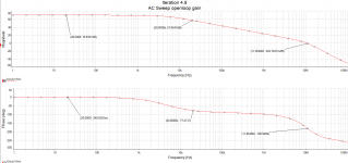
I tried the active loads and found the high frequency beheaviour to be an absolute mess, So I started minimizing paracitic capacitances. (Back to bc559s) Now, even without active loads on the jfets it yields 70dB openloop gain with minimal compensation. Now we are really talking.
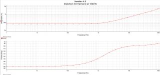
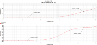
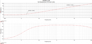
Only yesterday i figured out how to find harmonic distortion figures in NI multisim. I can plot it only for 2nd and 3rd harmonics. There's also an interactive tool that shows THD. With only 9dB of feedback it showed 1.2% at full blast at 20kHz.
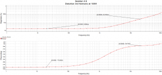
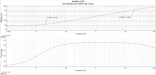
Now with about 27dB of feedback THD is below 0.1% (mostly 3rd, 2nd is gone completely) at 100W, 20kHz, given that all components are perfect. Can I assume higher order harmonics are smaller than the 3rd order ones?
Before I believed that feedback should be minimized and that an amp should perform okay before one applies feedback. Are these things still true? Already learning much duing this project, which I really appreciate. Thanks Russel.
I will post plots and the new schematic later.
Cheers and happy listening this weekend,
Ruben
Also I don't have any textbooks on more complex transistor toplogies whatsoever. We do work with 'control systems engineering' from N S Nice, and 'electronic devices' by Floyd, which have been somewhat useful. I have noticed cmos configurations to be among the most intricate, so I will check it out. Analog design is my favorite subject.
I tried the active loads and found the high frequency beheaviour to be an absolute mess, So I started minimizing paracitic capacitances. (Back to bc559s) Now, even without active loads on the jfets it yields 70dB openloop gain with minimal compensation. Now we are really talking.
Only yesterday i figured out how to find harmonic distortion figures in NI multisim. I can plot it only for 2nd and 3rd harmonics. There's also an interactive tool that shows THD. With only 9dB of feedback it showed 1.2% at full blast at 20kHz.
Now with about 27dB of feedback THD is below 0.1% (mostly 3rd, 2nd is gone completely) at 100W, 20kHz, given that all components are perfect. Can I assume higher order harmonics are smaller than the 3rd order ones?
Before I believed that feedback should be minimized and that an amp should perform okay before one applies feedback. Are these things still true? Already learning much duing this project, which I really appreciate. Thanks Russel.
I will post plots and the new schematic later.
Cheers and happy listening this weekend,
Ruben
Last edited:
15750hz is almost a tone but more of a "presence". That is the CRT oscillator
on old TV's .. BTW.
In the european PAL system the line frequency was 15625 Hz 🙂.
Even though 20k plus is beyond most people hearing, these fequencies still cantain energy that enters our ears correct? Though we cannot percieve these frequencies directly, they could still interact with frequencies we can hear right?
I suppose it is possible. I'm skeptical, unless there is huge acoustic content above 20 kHz.
I tried the active loads and found the high frequency beheaviour to be an absolute mess, So I started minimizing paracitic capacitances. (Back to bc559s) Now, even without active loads on the jfets it yields 70dB openloop gain with minimal compensation. Now we are really talking.
Gain in the input stage decreases stability, so what you say makes sense. It can be done, but stabilization requires a larger Ccomp. Also, your CMFB is made very twitchy, and possibly unstable. An increase in gain of the VAS makes the Ccomp you have work even better. It is a Miller capacitance, so increasing the gain of that transistor with a current source load increases the Miller multiplication.
Wait. I thought you said open loop gain was 70 dB now. That would be 47 dB of feedback, yes? Harmonics add as the square root of the sum of squares. If sqrt(H2^2 + H3^2) is most of the THD, then the higher harmonics are smaller in magnitude than those two.Only yesterday i figured out how to find harmonic distortion figures in NI multisim. I can plot it only for 2nd and 3rd harmonics. There's also an interactive tool that shows THD. With only 9dB of feedback it showed 1.2% at full blast at 20kHz.
Now with about 27dB of feedback THD is below 0.1% (mostly 3rd, 2nd is gone completely) at 100W, 20kHz, given that all components are perfect. Can I assume higher order harmonics are smaller than the 3rd order ones?
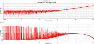
One of the properties of differential amplifiers is that even harmonics cancel. Even harmonics are generated from asymmetric non-linearity. Those cancel with differential output. Odd harmonics are generated from symmetric non-linearity (clipping, for example). You will still have those.
Before I believed that feedback should be minimized and that an amp should perform okay before one applies feedback. Are these things still true? Already learning much duing this project, which I really appreciate. Thanks Russel.
Highest linearity cannot be achieved without feedback. That can be local feedback, such as emitter degeneration or Miller capacitance and resistance. Or it can be global feedback--the resistor/capacitor network from output to input.
With global feedback, you have two choices. None or a lot. My rule of thumb is at least 40 dB at all the frequencies you care about. More is better, but getting above 60 dB at 20 kHz becomes quite difficult. It is important to have the best linearity you can before feedback, regardless of the amount applied.
Before feedback is applied, a key technique for high linearity is to keep the transistors' operating currents as constant as possible all across the voltage swing. That means a very high impedance at the output nodes of gain stages--the input stage and VAS. Current source loads give you that high impedance. Think about how the collector current in your VAS transistor changed with voltage swing when you had a resistor load. Compare that to the change in collector current with voltage swing using the current source load. That current source load gives you higher gain AND higher linearity.
I'm glad you are learning lots. Because you are actually building this thing, I'd like to see you build something great that will impress your friends.
iteration 4.9 and plots
"Gain in the input stage decreases stability, so what you say makes sense. It can be done, but stabilization requires a larger Ccomp. Also, your CMFB is made very twitchy, and possibly unstable. An increase in gain of the VAS makes the Ccomp you have work even better. It is a Miller capacitance, so increasing the gain of that transistor with a current source load increases the Miller multiplication."
What you mean here is when we use an active load on the jfets correct? Or is the CMFB too twithy the way it is now? I tuned it so squarewaves look tight.
And yes its 47dB feedback, that 27 was a brainfart.
Ive been thinking about asymmetric and symmetric non-linearity. In an interview with Steve Guttenberg Nelson Pass described he introduces some asymmetry his 0.8 amps to create some second harmonic. First off all THD should be low, though it seems people prefer a certain harmonic content, which seems to be a negative phase dominant second followed by decreasing higher order harmonics.
Once the third harmonics are brought down to a minimum, can we just introduce some asymmetry in my design to yield some second? Or is this crazy?
I added the plots harvested from the current circuit. I think it looks pretty sweet now.
Cheers,
Ruben
Attachments
Looks great, Ruben.
I suppose you could try to unbalance the circuit to create some 2nd harmonic. Easiest way would be to make R1 and R2 slightly different. I think no more than 6 dB higher than the 3rd harmonic would be enough.
You could aim for that in simulation, and then try it when you build the circuit. R1=R2 and R1/R2 mismatched. See if you can hear a difference, and which one you like better.
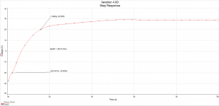
See if you can measure slew rate. I'm curious. Just input a largish square wave and see what the slopes are on the output square wave. I'm guessing the amp is very fast.
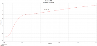
Slew Rate
The first few volts are very fast, the last ones are very slow. I'm using 4Vpp input square.
Btw, I should probably try to get higher openloop gain or reduce closed loop gain. since at 20kHz there's only 34dB of feedback. My 'preamp' (a little ES100 atm) can output 6Vpp, so less Av won't hurt I guess.
Cheers,
Ruben
Attachments
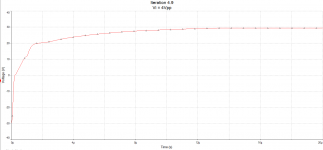
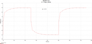
That looks about right for having a resistor load on the input pair. You are charging the Miller caps through a resistor. The JFET discharges them. Differentially, you are limited by whichever side is charging through the resistor.
Still, this is respectably fast. You get from -20V to 20V in about 1.5 us. That's about 27V/us.
Still, this is respectably fast. You get from -20V to 20V in about 1.5 us. That's about 27V/us.
The last passive load has fallen
Hi All,
So the amp could be faster if the miller caps could be discharged faster, so I tried running more current through the jfets, pushed up closed loop gain a bit while reducing closed loop gain slightly and gained a little speed. Also running some less bias on the output stage. All this brought THD downto 0.033% at 20k at 100W, still using resistors at the drains of the jfets. The step response looked quite messy though.
Eventually I got a stable amp using active loads, which resulted in more low frequency openloop gain and a little less open loop gain at 20k than before.
Despite less feedback at 20k, it is now marginally faster and THD is lower still. I wish I could give it more openloop gain at 20k without making it instable. With Ccomp being 18pF, THD was 0.017% at 100W, 20k, though bodeplots showed instability.
With Ccomp of 47pF, THD would be 0.024% half of which is third order, lower than my ears will ever hear.
Basic vas or not, these specs look pretty good to me. Next question is how it would sound. I did not menage to give it dominant second without getting offset on the outputs and if there's no dominant second there better not be any at all.
Should I try to squeeze more out of this design or move on to ordering parts? I'm more tempted then ever.
Have a great sounding weekend and cheers,
Ruben
Attachments
For stability, I am not sure you are looking at open-loop gain of the amplifier, or open-loop gain of the loop. Are you just looking at (Vo2-Vo1)/(Vi2-Vi1). Or are you looking at that gain times the feedback attenuation?
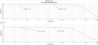
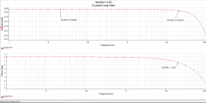
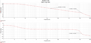
You should be looking at the gain of the loop. In other words look at the point on your open-loop Bode plot where the open loop gain crosses the close-loop gain. At 20.8 dB
Looking at open-loop gain, stability is determined at the point where gain crosses 20.8 dB. You are very stable there, with a PM > 80 deg. I bet you can reduce your compensation caps from 47 pF to 33 or maybe even 22 pF, and still have good stability
That'd be great haha. Right now I am looking at (+Vo-(-Vo))/(+Vi-(-Vi)) when the 330ohm fb resistors are disconnected. Making sure that at -180 degrees the openloop gain is less below 0. Maybe I misunderstood?
- Home
- Amplifiers
- Solid State
- Class AB diff-amp design